HP ProBook 6360b HP ProBook 6360b Notebook PC - Maintenance and Service Guide - Page 101
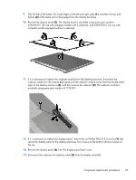
If it is necessary to replace the display panel, remove the six Phillips PM2.5×5.0 screws
 |
View all HP ProBook 6360b manuals
Add to My Manuals
Save this manual to your list of manuals |
Page 101 highlights
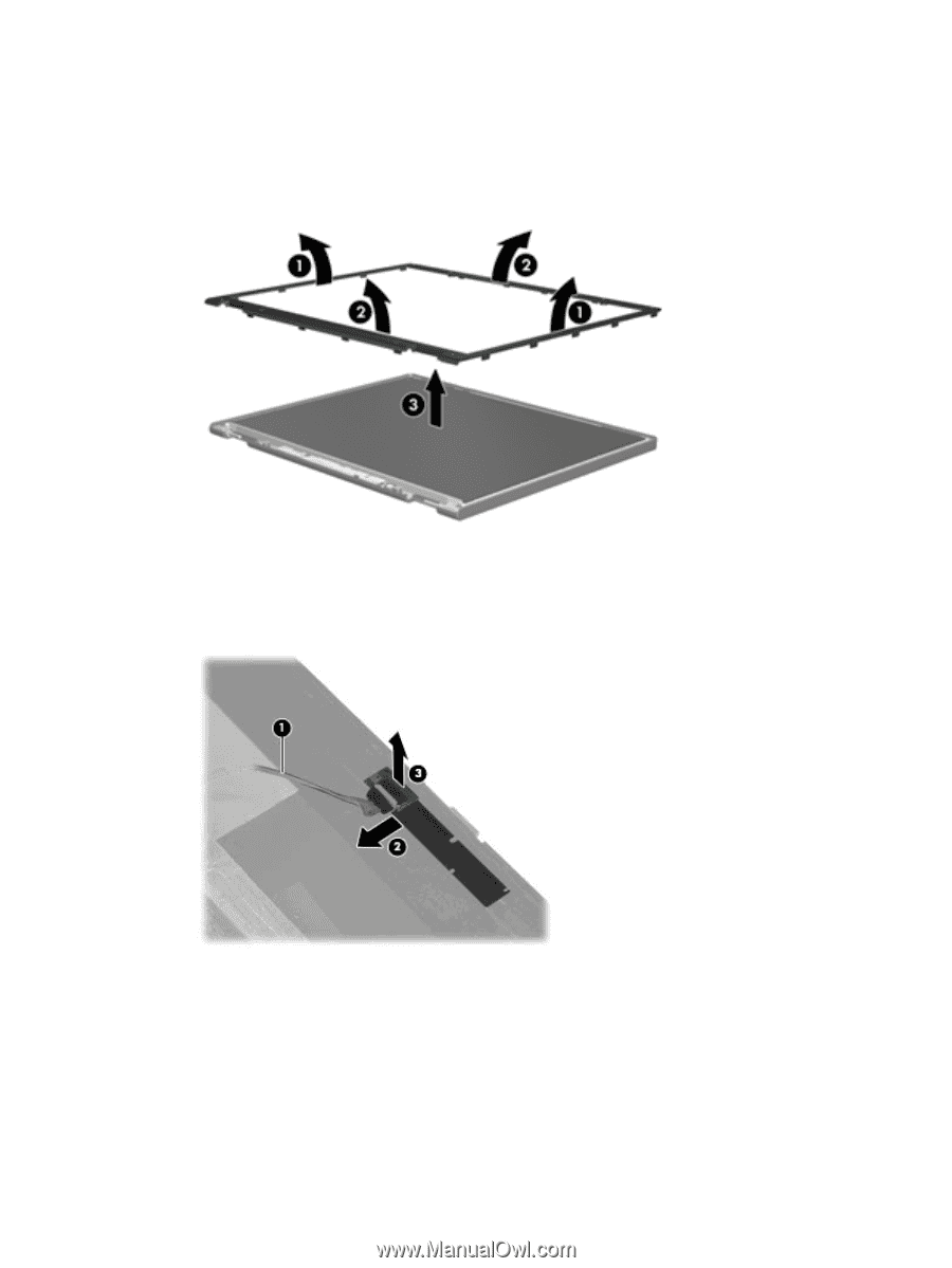
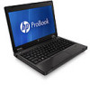
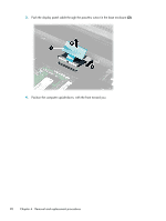
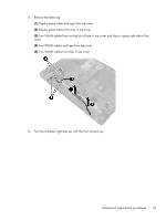
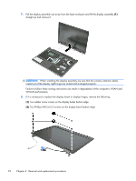
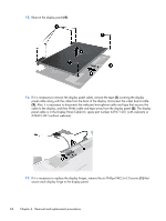
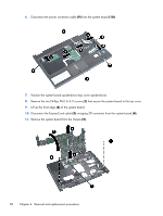
9. Flex the top of the bezel, the inside edges of the left and right sides (1), and then the top and bottom (2) of the bezel until it disengages from the display enclosure. 10. Remove the display bezel (3). The display bezel is available using spare part numbers 639469-001 (for use with computer models with a webcam), and 639470-001 (for use with computer models equipped without a webcam). 11. If it is necessary to replace the webcam module from the display enclosure, disconnect the webcam cable from the module (1), gently pull the webcam module away from the double-sided tape on the display enclosure (2), and then remove the webcam (3). The webcam module is available using spare part number 641735-001. 12. If it is necessary to replace the display panel, remove the six Phillips PM2.5×5.0 screws (1) that secure the display panel to the display enclosure, four screws on the bottom and two screws on the top. 13. Remove the display panel (2) from the display panel back cover. 14. Disconnect the webcam/microphone cable (3) from the display assembly. Component replacement procedures 93
-
 1
1 -
2
-
3
-
4
-
5
-
6
-
7
-
8
-
9
-
10
-
11
-
12
-
13
-
14
-
15
-
16
-
17
-
18
-
19
-
20
-
21
-
22
-
23
-
24
-
25
-
26
-
27
-
28
-
29
-
30
-
31
-
32
-
33
-
34
-
35
-
36
-
37
-
38
-
39
-
40
-
41
-
42
-
43
-
44
-
45
-
46
-
47
-
48
-
49
-
50
-
51
-
52
-
53
-
54
-
55
-
56
-
57
-
58
-
59
-
60
-
61
-
62
-
63
-
64
-
65
-
66
-
67
-
68
-
69
-
70
-
71
-
72
-
73
-
74
-
75
-
76
-
77
-
78
-
79
-
80
-
81
-
82
-
83
-
84
-
85
-
86
-
87
-
88
-
89
-
90
-
91
-
92
-
93
-
94
-
95
-
 96
96 -
 97
97 -
 98
98 -
 99
99 -
 100
100 -
 101
101 -
 102
102 -
 103
103 -
 104
104 -
 105
105 -
 106
106 -
107
-
108
-
109
-
110
-
111
-
112
-
113
-
114
-
115
-
116
-
117
-
118
-
119
-
120
-
121
-
122
-
123
-
124
-
125
-
126
-
127
-
128
-
129
-
130
-
131
-
132
-
133
-
134
-
135
-
136
-
137
-
138
-
139
-
140
-
141
-
142
-
143
-
144
-
145
-
146
-
147
-
148
-
149
-
150
-
151
-
152
-
153
-
154
-
155
-
156
-
157
 |
 |