HP ProBook 6360b HP ProBook 6360b Notebook PC - Maintenance and Service Guide - Page 111
Display assembly see, Remove the Fingerprint reader board assembly
 |
View all HP ProBook 6360b manuals
Add to My Manuals
Save this manual to your list of manuals |
Page 111 highlights
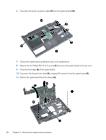
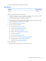
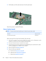
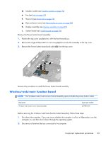
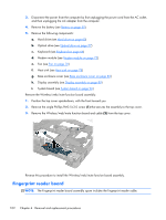
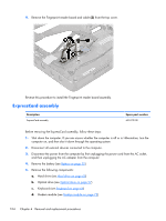
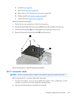
Description Fingerprint reader board assembly Spare part number 651913-001 Before removing the Fingerprint reader board assembly, follow these steps: 1. Shut down the computer. If you are unsure whether the computer is off or in Hibernation, turn the computer on, and then shut it down through the operating system. 2. Disconnect all external devices connected to the computer. 3. Disconnect the power from the computer by first unplugging the power cord from the AC outlet, and then unplugging the AC adapter from the computer. 4. Remove the battery (see Battery on page 50) 5. Remove the following components: a. Hard drive (see Hard drive on page 60) b. Optical drive (see Optical drive on page 57) c. Keyboard (see Keyboard on page 66) d. Modem module (see Modem module on page 72) e. Fan (see Fan on page 76) f. Heat sink (see Heat sink on page 78) g. Base enclosure cover (see Base enclosure cover on page 82) h. Display assembly (see Display assembly on page 89) i. System board (see System board on page 96) Remove the Fingerprint reader board assembly: 1. Position the top cover upside-down, with the front toward you. 2. Remove the single Phillips PM2.5×3.0 screw (1) that secures the assembly to the top cover. 3. Slide the bracket (2) to remove the clips in top cover and lift off unit. Component replacement procedures 103
-
 1
1 -
2
-
3
-
4
-
5
-
6
-
7
-
8
-
9
-
10
-
11
-
12
-
13
-
14
-
15
-
16
-
17
-
18
-
19
-
20
-
21
-
22
-
23
-
24
-
25
-
26
-
27
-
28
-
29
-
30
-
31
-
32
-
33
-
34
-
35
-
36
-
37
-
38
-
39
-
40
-
41
-
42
-
43
-
44
-
45
-
46
-
47
-
48
-
49
-
50
-
51
-
52
-
53
-
54
-
55
-
56
-
57
-
58
-
59
-
60
-
61
-
62
-
63
-
64
-
65
-
66
-
67
-
68
-
69
-
70
-
71
-
72
-
73
-
74
-
75
-
76
-
77
-
78
-
79
-
80
-
81
-
82
-
83
-
84
-
85
-
86
-
87
-
88
-
89
-
90
-
91
-
92
-
93
-
94
-
95
-
96
-
97
-
98
-
99
-
100
-
101
-
102
-
103
-
104
-
105
-
 106
106 -
 107
107 -
 108
108 -
 109
109 -
 110
110 -
 111
111 -
 112
112 -
 113
113 -
 114
114 -
 115
115 -
 116
116 -
117
-
118
-
119
-
120
-
121
-
122
-
123
-
124
-
125
-
126
-
127
-
128
-
129
-
130
-
131
-
132
-
133
-
134
-
135
-
136
-
137
-
138
-
139
-
140
-
141
-
142
-
143
-
144
-
145
-
146
-
147
-
148
-
149
-
150
-
151
-
152
-
153
-
154
-
155
-
156
-
157
 |
 |