HP ProBook 6360b HP ProBook 6360b Notebook PC - Maintenance and Service Guide - Page 105
Position the top cover right-side up, with the front toward you., Disconnect the power button cable
 |
View all HP ProBook 6360b manuals
Add to My Manuals
Save this manual to your list of manuals |
Page 105 highlights
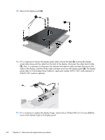
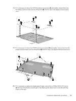
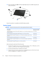
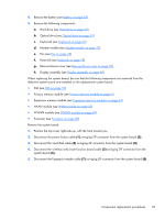
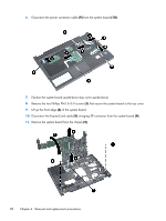
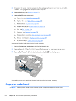
4. Remove the battery (see Battery on page 50). 5. Remove the following components: a. Hard drive (see Hard drive on page 60) b. Optical drive (see Optical drive on page 57) c. Keyboard (see Keyboard on page 66) d. Modem module (see Modem module on page 72) e. Fan (see Fan on page 76) f. Heat sink (see Heat sink on page 78) g. Base enclosure cover (see Base enclosure cover on page 82) h. Display assembly (see Display assembly on page 89) When replacing the system board, be sure that the following components are removed from the defective system board and installed on the replacement system board: ● SIM (see SIM on page 51) ● Primary memory module (see Primary memory module on page 74 ● Expansion memory module (see Expansion memory modules on page 64) ● WLAN module (see WLAN module on page 52) ● WWAN module (see WWAN module on page 69) ● Processor (see Processor on page 80) Remove the system board: 1. Position the top cover right-side up, with the front toward you. 2. Disconnect the power button cable (1) swinging ZIF connector from the system board (2). 3. Disconnect the TouchPad cable (3) swinging ZIF connector from the system board (4). 4. Disconnect the wireless/web/mute function board cable (5) swinging ZIF connector from the system board (6). 5. Disconnect the fingerprint reader cable (7) swinging ZIF connector from the system board (8). Component replacement procedures 97
-
 1
1 -
2
-
3
-
4
-
5
-
6
-
7
-
8
-
9
-
10
-
11
-
12
-
13
-
14
-
15
-
16
-
17
-
18
-
19
-
20
-
21
-
22
-
23
-
24
-
25
-
26
-
27
-
28
-
29
-
30
-
31
-
32
-
33
-
34
-
35
-
36
-
37
-
38
-
39
-
40
-
41
-
42
-
43
-
44
-
45
-
46
-
47
-
48
-
49
-
50
-
51
-
52
-
53
-
54
-
55
-
56
-
57
-
58
-
59
-
60
-
61
-
62
-
63
-
64
-
65
-
66
-
67
-
68
-
69
-
70
-
71
-
72
-
73
-
74
-
75
-
76
-
77
-
78
-
79
-
80
-
81
-
82
-
83
-
84
-
85
-
86
-
87
-
88
-
89
-
90
-
91
-
92
-
93
-
94
-
95
-
96
-
97
-
98
-
99
-
 100
100 -
 101
101 -
 102
102 -
 103
103 -
 104
104 -
 105
105 -
 106
106 -
 107
107 -
 108
108 -
 109
109 -
 110
110 -
111
-
112
-
113
-
114
-
115
-
116
-
117
-
118
-
119
-
120
-
121
-
122
-
123
-
124
-
125
-
126
-
127
-
128
-
129
-
130
-
131
-
132
-
133
-
134
-
135
-
136
-
137
-
138
-
139
-
140
-
141
-
142
-
143
-
144
-
145
-
146
-
147
-
148
-
149
-
150
-
151
-
152
-
153
-
154
-
155
-
156
-
157
 |
 |