HP ProBook 6360b HP ProBook 6360b Notebook PC - Maintenance and Service Guide - Page 114
Position the top cover upside-down, with the front toward you., Remove the RJ-11 connector cable
 |
View all HP ProBook 6360b manuals
Add to My Manuals
Save this manual to your list of manuals |
Page 114 highlights
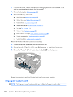
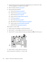
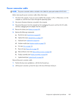
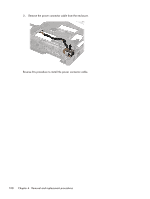
3. Disconnect the power from the computer by first unplugging the power cord from the AC outlet, and then unplugging the AC adapter from the computer. 4. Remove the battery (see Battery on page 50). 5. Remove the following components: a. Hard drive (see Hard drive on page 60) b. Optical drive (see Optical drive on page 57) c. Keyboard (see Keyboard on page 66) d. Modem module (see Modem module on page 72) e. Fan (see Fan on page 76) f. Heat sink (see Heat sink on page 78) g. Base enclosure cover (see Base enclosure cover on page 82) h. Display assembly (see Display assembly on page 89) i. System board (see System board on page 96) Remove the RJ-11 connector cable: 1. Position the top cover upside-down, with the front toward you. 2. Remove the RJ-11 connector (1) from the clip built into the top cover. 3. Remove the RJ-11 connector cable from the clips and routing channel (2) built into the top cover. 4. Remove the RJ-11 connector cable from the top cover. Reverse this procedure to install the RJ-11 connector cable. 106 Chapter 4 Removal and replacement procedures
-
 1
1 -
2
-
3
-
4
-
5
-
6
-
7
-
8
-
9
-
10
-
11
-
12
-
13
-
14
-
15
-
16
-
17
-
18
-
19
-
20
-
21
-
22
-
23
-
24
-
25
-
26
-
27
-
28
-
29
-
30
-
31
-
32
-
33
-
34
-
35
-
36
-
37
-
38
-
39
-
40
-
41
-
42
-
43
-
44
-
45
-
46
-
47
-
48
-
49
-
50
-
51
-
52
-
53
-
54
-
55
-
56
-
57
-
58
-
59
-
60
-
61
-
62
-
63
-
64
-
65
-
66
-
67
-
68
-
69
-
70
-
71
-
72
-
73
-
74
-
75
-
76
-
77
-
78
-
79
-
80
-
81
-
82
-
83
-
84
-
85
-
86
-
87
-
88
-
89
-
90
-
91
-
92
-
93
-
94
-
95
-
96
-
97
-
98
-
99
-
100
-
101
-
102
-
103
-
104
-
105
-
106
-
107
-
108
-
 109
109 -
 110
110 -
 111
111 -
 112
112 -
 113
113 -
 114
114 -
 115
115 -
 116
116 -
 117
117 -
 118
118 -
 119
119 -
120
-
121
-
122
-
123
-
124
-
125
-
126
-
127
-
128
-
129
-
130
-
131
-
132
-
133
-
134
-
135
-
136
-
137
-
138
-
139
-
140
-
141
-
142
-
143
-
144
-
145
-
146
-
147
-
148
-
149
-
150
-
151
-
152
-
153
-
154
-
155
-
156
-
157
 |
 |