HP ProLiant ML310e HP ProLiant ML310e Gen8 Server User Guide - Page 30
Hardware options installation, Introduction, Drive options, Drive installation guidelines
 |
View all HP ProLiant ML310e manuals
Add to My Manuals
Save this manual to your list of manuals |
Page 30 highlights
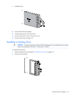
Hardware options installation Introduction If more than one option is being installed, read the installation instructions for all the hardware options and identify similar steps to streamline the installation process. WARNING: To reduce the risk of personal injury from hot surfaces, allow the drives and the internal system components to cool before touching them. CAUTION: To prevent damage to electrical components, properly ground the server before beginning any installation procedure. Improper grounding can cause electrostatic discharge. Drive options The server supports up to four non-hot-plug or hot-plug LFF drives and up to eight hot-plug SFF drives. The embedded storage controller supports SATA drive installation only. For SAS drive installation, install the storage controller card and Mini-SAS cable option kits. The storage controller card option supports both SATA and SAS drives. Drive installation guidelines When adding hard drives to the server, observe the following general guidelines: • The system automatically sets all drive numbers. • Populate drive bays, based on the drive numbering sequence. Start from the drive bay with the lowest device number ("Drive numbering" on page 14). • When drives are grouped together into the same drive array, they must be of the same capacity to provide the greatest storage space efficiency. Installing a non-hot-plug drive CAUTION: To prevent improper cooling and thermal damage, do not operate the server unless all bays are populated with either a component or a blank. To install the component: 1. Power down the server (on page 18). 2. Remove all power: a. Disconnect each power cord from the power source. b. Disconnect each power cord from the server. 3. Unlock and open the tower bezel ("Unlock the tower bezel" on page 19). Hardware options installation 30
-
 1
1 -
2
-
3
-
4
-
5
-
6
-
7
-
8
-
9
-
10
-
11
-
12
-
13
-
14
-
15
-
16
-
17
-
18
-
19
-
20
-
21
-
22
-
23
-
24
-
 25
25 -
 26
26 -
 27
27 -
 28
28 -
 29
29 -
 30
30 -
 31
31 -
 32
32 -
 33
33 -
 34
34 -
 35
35 -
36
-
37
-
38
-
39
-
40
-
41
-
42
-
43
-
44
-
45
-
46
-
47
-
48
-
49
-
50
-
51
-
52
-
53
-
54
-
55
-
56
-
57
-
58
-
59
-
60
-
61
-
62
-
63
-
64
-
65
-
66
-
67
-
68
-
69
-
70
-
71
-
72
-
73
-
74
-
75
-
76
-
77
-
78
-
79
-
80
-
81
-
82
-
83
-
84
-
85
-
86
-
87
-
88
-
89
-
90
-
91
-
92
-
93
-
94
-
95
-
96
-
97
-
98
-
99
-
100
-
101
-
102
-
103
-
104
-
105
-
106
-
107
 |
 |
