HP ProLiant ML310e HP ProLiant ML310e Gen8 Server User Guide - Page 46
Single-rank and dual-rank DIMMs, Memory subsystem architecture, ECC memory, Description, Definition
 |
View all HP ProLiant ML310e manuals
Add to My Manuals
Save this manual to your list of manuals |
Page 46 highlights
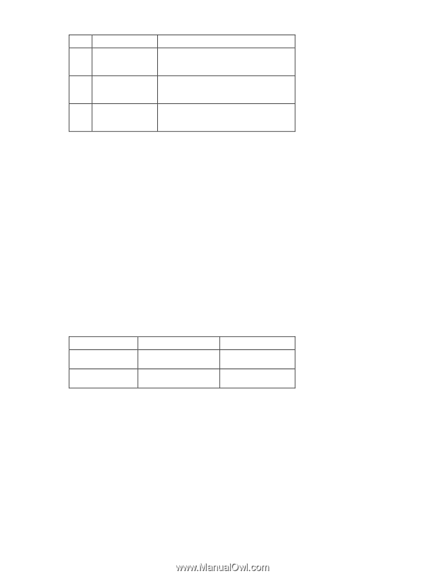
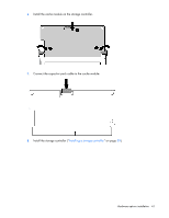
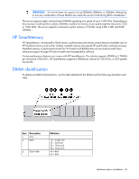
Item Description 4 Voltage rating 5 Memory speed 6 DIMM type Definition L = Low voltage (1.35V) U = Ultra low voltage (1.25V) Blank or omitted = Standard 12800 = 1600-MT/s 10600 = 1333-MT/s 8500 = 1066-MT/s R = RDIMM (registered) E = UDIMM (unbuffered with ECC) L = LRDIMM (load reduced) For the latest supported memory information, see the QuickSpecs on the HP website (http://h18000.www1.hp.com/products/quickspecs/ProductBulletin.html). At the website, choose the geographic region, and then locate the product by name or product category. Single-rank and dual-rank DIMMs DIMM configuration requirements are based on these classifications: • Single-rank DIMM-One set of memory chips that is accessed while writing to or reading from the memory. • Dual-rank DIMM-Two single-rank DIMMs on the same module, with only one rank accessible at a time. The server memory control subsystem selects the proper rank within the DIMM when writing to or reading from the DIMM. Dual-rank DIMMs provide the greatest capacity with the existing memory technology. For example, if current DRAM technology supports 2-GB single-rank DIMMs, a dual-rank DIMM would be 4 GB. Memory subsystem architecture The memory subsystem in this server is divided into channels. Each channel supports two DIMM slots. Channel 1 2 Population order C A D B Slot number 1 2 3 4 DIMM slots in this server are identified by number and by letter. Letters identify the population order. Slot numbers are reported by ROM messages during boot and for error reporting. For the DIMM slot locations, see "DIMM slot locations (on page 12)." ECC memory The server supports the standard ECC memory correction mode. Standard ECC can correct single-bit memory errors and detect multibit memory errors. When multibit errors are detected, the error is signaled to the server and causes the server to halt. Hardware options installation 46
-
 1
1 -
2
-
3
-
4
-
5
-
6
-
7
-
8
-
9
-
10
-
11
-
12
-
13
-
14
-
15
-
16
-
17
-
18
-
19
-
20
-
21
-
22
-
23
-
24
-
25
-
26
-
27
-
28
-
29
-
30
-
31
-
32
-
33
-
34
-
35
-
36
-
37
-
38
-
39
-
40
-
 41
41 -
 42
42 -
 43
43 -
 44
44 -
 45
45 -
 46
46 -
 47
47 -
 48
48 -
 49
49 -
 50
50 -
 51
51 -
52
-
53
-
54
-
55
-
56
-
57
-
58
-
59
-
60
-
61
-
62
-
63
-
64
-
65
-
66
-
67
-
68
-
69
-
70
-
71
-
72
-
73
-
74
-
75
-
76
-
77
-
78
-
79
-
80
-
81
-
82
-
83
-
84
-
85
-
86
-
87
-
88
-
89
-
90
-
91
-
92
-
93
-
94
-
95
-
96
-
97
-
98
-
99
-
100
-
101
-
102
-
103
-
104
-
105
-
106
-
107
 |
 |