HP ProLiant ML310e HP ProLiant ML310e Gen8 Server User Guide - Page 59
The default and redundant power supplies in the server must have the same output
 |
View all HP ProLiant ML310e manuals
Add to My Manuals
Save this manual to your list of manuals |
Page 59 highlights
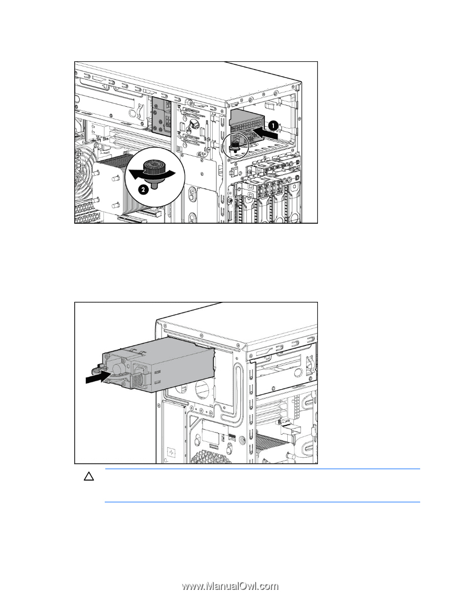
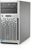
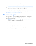
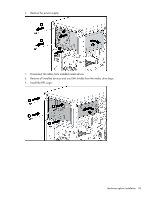
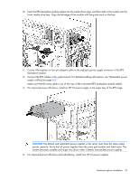
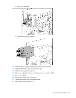
10. Insert the RPS backplane module cables into the media drive cage, and then slide in the module into the lower media drive bay. Align the left edge of the module with the guide mark on the bay. 11. Connect the eight-pin to four-pin adapter cable to the eight-pin power supply connector of the RPS backplane module. 12. Connect the RPS cables to the system board. For detailed cabling information, see "Redundant power supply cabling (on page 65)." Make sure that the extra cable is out of the way of the connected RPS backplane module cables. 13. For improved power efficiency, install an HP CS power supply in the upper bay of the RPS cage. CAUTION: The default and redundant power supplies in the server must have the same output power capacity. Verify that all power supplies have the same part number and label color. The system becomes unstable and might shut down when it detects mismatched power supplies. 14. For improved power efficiency and redundancy, install two HP CS power supplies: Hardware options installation 59
-
 1
1 -
2
-
3
-
4
-
5
-
6
-
7
-
8
-
9
-
10
-
11
-
12
-
13
-
14
-
15
-
16
-
17
-
18
-
19
-
20
-
21
-
22
-
23
-
24
-
25
-
26
-
27
-
28
-
29
-
30
-
31
-
32
-
33
-
34
-
35
-
36
-
37
-
38
-
39
-
40
-
41
-
42
-
43
-
44
-
45
-
46
-
47
-
48
-
49
-
50
-
51
-
52
-
53
-
 54
54 -
 55
55 -
 56
56 -
 57
57 -
 58
58 -
 59
59 -
 60
60 -
 61
61 -
 62
62 -
 63
63 -
 64
64 -
65
-
66
-
67
-
68
-
69
-
70
-
71
-
72
-
73
-
74
-
75
-
76
-
77
-
78
-
79
-
80
-
81
-
82
-
83
-
84
-
85
-
86
-
87
-
88
-
89
-
90
-
91
-
92
-
93
-
94
-
95
-
96
-
97
-
98
-
99
-
100
-
101
-
102
-
103
-
104
-
105
-
106
-
107
 |
 |