HP ProLiant ML310e HP ProLiant ML310e Gen8 Server User Guide - Page 40
Installing the FBWC module and capacitor pack, HP Smart Array Controllers for HP ProLiant
 |
View all HP ProLiant ML310e manuals
Add to My Manuals
Save this manual to your list of manuals |
Page 40 highlights
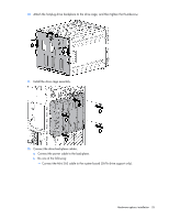
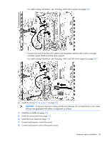
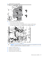
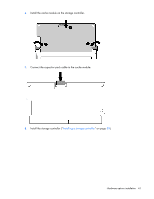
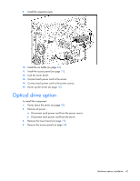
2. Remove all power: a. Disconnect each power cord from the power source. b. Disconnect each power cord from the server. 3. Unlock the tower bezel (on page 19). 4. Remove the access panel (on page 20). 5. Remove the air baffle (on page 21). 6. If necessary, disconnect the Mini-SAS cable from the system board. 7. Install the storage controller. 8. Connect all necessary internal and external cabling to the option. For more information on these cabling requirements, see the documentation that ships with the option. For internal cable routing information in different drive configurations, see "Storage cabling (on page 61)." 9. Install the air baffle (on page 22). 10. Install the access panel (on page 21). 11. Install the drives ("Drive options" on page 30). CAUTION: To prevent improper cooling and thermal damage, do not operate the chassis unless all bays are populated with a component or a blank. 12. Lock the tower bezel. 13. Connect each power cord to the server. 14. Connect each power cord to the power source. 15. Power up the server (on page 18). For more information about the controller and its features, see the HP Smart Array Controllers for HP ProLiant Servers User Guide on the HP website (http://www.hp.com/support/SAC_UG_ProLiantServers_en). To configure arrays, see the Configuring Arrays on HP Smart Array Controllers Reference Guide on the HP website (http://www.hp.com/support/CASAC_RG_en). Upgrade options exist for the integrated array controller. For a list of supported options, see the QuickSpecs on the HP website (http://www.hp.com/support). Installing the FBWC module and capacitor pack CAUTION: In systems that use external data storage, be sure that the server is the first unit to be powered down and the last to be powered back up. Taking this precaution ensures that the system does not erroneously mark the drives as failed when the server is powered up. To install the component: 1. Power down the server (on page 18). 2. Remove all power: a. Disconnect each power cord from the power source. b. Disconnect each power cord from the server. 3. Unlock the tower bezel (on page 19). 4. Remove the access panel (on page 20). 5. Remove the air baffle (on page 21). Hardware options installation 40
-
 1
1 -
2
-
3
-
4
-
5
-
6
-
7
-
8
-
9
-
10
-
11
-
12
-
13
-
14
-
15
-
16
-
17
-
18
-
19
-
20
-
21
-
22
-
23
-
24
-
25
-
26
-
27
-
28
-
29
-
30
-
31
-
32
-
33
-
34
-
 35
35 -
 36
36 -
 37
37 -
 38
38 -
 39
39 -
 40
40 -
 41
41 -
 42
42 -
 43
43 -
 44
44 -
 45
45 -
46
-
47
-
48
-
49
-
50
-
51
-
52
-
53
-
54
-
55
-
56
-
57
-
58
-
59
-
60
-
61
-
62
-
63
-
64
-
65
-
66
-
67
-
68
-
69
-
70
-
71
-
72
-
73
-
74
-
75
-
76
-
77
-
78
-
79
-
80
-
81
-
82
-
83
-
84
-
85
-
86
-
87
-
88
-
89
-
90
-
91
-
92
-
93
-
94
-
95
-
96
-
97
-
98
-
99
-
100
-
101
-
102
-
103
-
104
-
105
-
106
-
107
 |
 |
