HP Split 13-m001xx HP Split 13 x2 PC Maintenance and Service Guide
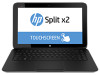
HP Split 13-m001xx Manual
 |
View all HP Split 13-m001xx manuals
Add to My Manuals
Save this manual to your list of manuals |
HP Split 13-m001xx manual content summary:
- HP Split 13-m001xx | HP Split 13 x2 PC Maintenance and Service Guide - Page 1
HP Split 13 x2 PC Maintenance and Service Guide IMPORTANT! This document is intended for HP authorized service providers only. - HP Split 13-m001xx | HP Split 13 x2 PC Maintenance and Service Guide - Page 2
such products and services. Nothing herein should be construed as constituting an additional warranty. HP shall not be liable for technical or editorial errors or omissions contained herein. First Edition: October 2013 Document Part Number: 741816-001 Product notice This guide describes features - HP Split 13-m001xx | HP Split 13 x2 PC Maintenance and Service Guide - Page 3
Self-Repair Parts CAUTION: Your computer includes parts that should only be accessed by an authorized service provider. Accessing parts described in the chapter titled, "Removal and replacement procedures for Authorized Service Provider only parts," can damage the computer or void your warranty. iii - HP Split 13-m001xx | HP Split 13 x2 PC Maintenance and Service Guide - Page 4
iv Important Notice about Customer Self-Repair Parts - HP Split 13-m001xx | HP Split 13 x2 PC Maintenance and Service Guide - Page 5
Safety warning notice WARNING! To reduce the possibility of heat-related injuries or of overheating the device, do not place the device directly on your lap. Use the device only on a hard, flat surface. Do not allow another hard surface, such as an adjoining optional printer, or a soft surface, such - HP Split 13-m001xx | HP Split 13 x2 PC Maintenance and Service Guide - Page 6
vi Safety warning notice - HP Split 13-m001xx | HP Split 13 x2 PC Maintenance and Service Guide - Page 7
Miscellaneous parts ...22 Sequential part number listing ...23 4 Removal and replacement procedures preliminary requirements 27 Tools required ...27 Service considerations ...27 Plastic parts ...27 Cables and connectors ...28 Drive handling ...28 Grounding guidelines ...29 Electrostatic discharge - HP Split 13-m001xx | HP Split 13 x2 PC Maintenance and Service Guide - Page 8
Base enclosure ...33 Hard drive ...34 Hinge assembly ...36 Battery ...37 HDMI board ...39 Hard drive cable ...40 USB board ...41 Touchpad board ...42 Power connector ...43 Weight ...44 Tablet components ...45 Display rear cover ...45 Battery cable ...46 Memory module ...47 Fan ...48 Heat sink ...49 - HP Split 13-m001xx | HP Split 13 x2 PC Maintenance and Service Guide - Page 9
Downloading HP PC Hardware Diagnostics (UEFI) to a USB device 78 7 Specifications ...79 Computer specifications ...79 33.8-cm (13.3-in), HD display specifications ...80 8 Backing up, restoring, and recovering ...81 Creating recovery media and backups ...81 Creating HP Recovery media ...82 Restore - HP Split 13-m001xx | HP Split 13 x2 PC Maintenance and Service Guide - Page 10
(1366×768), slim 3.2-mm. UWVA, 200 nits Supports 16:9 wide aspect ratio Support for eDP, touchscreen, multi-touch enabled Supports up to 8-GB system memory No support for 32-bit operating system DDR3L-1600-MHz, single channel support Supports the following configurations: 8192 (8192 × 1) 4096 (4096 - HP Split 13-m001xx | HP Split 13 x2 PC Maintenance and Service Guide - Page 11
eCompass Integrated WLAN options by way of wireless module Dual antennas Supports the following WLAN formats: Broadcom 4352 802.11 a/c + combo jack Docking connector (to tablet) DC-in port HDMI v1.4a supporting up to 1080p @ 60 Hz Full size, dura coat, island-style keyboard Taps enabled as - HP Split 13-m001xx | HP Split 13 x2 PC Maintenance and Service Guide - Page 12
Category Power requirements Operating syste m Serviceability Description Multi-touch gestures enabled Supports the following HP AC adapters: 45-W Smart nPFC, 3-pin, 4.5-mm connector, 90-degree plug design 65-W EM Smart nPFC, 3-pin, 4.5-mm connector, 90-degree plug - HP Split 13-m001xx | HP Split 13 x2 PC Maintenance and Service Guide - Page 13
. NOTE: When a device is connected to the jack, the computer speakers are disabled. NOTE: Be sure that the device cable has a 4-conductor connector that supports both audio-out (headphone) and audio-in (microphone). NOTE: Stand-alone microphones and headphones with separate microphone jacks are not - HP Split 13-m001xx | HP Split 13 x2 PC Maintenance and Service Guide - Page 14
Component (1) (2) (3) (4) (5) (6) Description Internal microphones (2) Webcam light HP TrueVision Full HD Webcam Ambient light sensor Speakers (2) HDMI port Record sound. On: The webcam is in use. Records video, captures still photographs, allows you to video conference and chat online using - HP Split 13-m001xx | HP Split 13 x2 PC Maintenance and Service Guide - Page 15
. NOTE: When a device is connected to the jack, the computer speakers are disabled. NOTE: Be sure that the device cable has a 4conductor connector that supports both audioout (headphone) and audio-in (microphone). NOTE: Stand-alone microphones and headphones with separate microphone jacks are not - HP Split 13-m001xx | HP Split 13 x2 PC Maintenance and Service Guide - Page 16
Tablet edge components Components (1) Power button (2) Alignment post connectors (2) (3) Power connector (4) AC adapter/Battery light Description ● When the computer is off, press the button to turn on the tablet. ● When the computer is on, press the button briefly to initiate Sleep. ● When - HP Split 13-m001xx | HP Split 13 x2 PC Maintenance and Service Guide - Page 17
both audio-out (headphone) and audio-in (microphone). NOTE: Stand-alone microphones and headphones with separate microphone jacks are not supported. Supports micro Secure Digital (SD) memory cards. Enables airflow to cool internal components. NOTE: The computer fan starts up automatically to - HP Split 13-m001xx | HP Split 13 x2 PC Maintenance and Service Guide - Page 18
Display Component (1) (2) (3) (4) WLAN antennas (2)* Internal microphones (2) Webcam light HP TrueVision Full HD Webcam Description Send and receive wireless signals. Record audio, automatically filtering out the noise around you and cancelling echoes. On: The webcam is on. Records video, - HP Split 13-m001xx | HP Split 13 x2 PC Maintenance and Service Guide - Page 19
Keyboard dock Top Component (1) (2) (3) Alignment posts Release latch Docking connector Description Align and attach the tablet to the keyboard dock. Releases the tablet from the keyboard dock. To release the tablet, slide the release latch to the left. Connects the tablet to the keyboard dock. - HP Split 13-m001xx | HP Split 13 x2 PC Maintenance and Service Guide - Page 20
TouchPad Component (1) TouchPad zone (2) Left TouchPad button (3) Right TouchPad button Description Reads your finger gesture to move the pointer or activate items on the screen. Functions like the left button of an external mouse. Functions like the right button on an external mouse. - HP Split 13-m001xx | HP Split 13 x2 PC Maintenance and Service Guide - Page 21
Lights Component (1) Caps lock light (2) Mute light (3) Wireless light Description ● White: Caps lock is on. ● Off: Caps lock is off. ● Amber: Computer sound is off. ● Off: Computer sound is on. ● White: An integrated wireless device, such as a wireless local area network (WLAN) device and/or - HP Split 13-m001xx | HP Split 13 x2 PC Maintenance and Service Guide - Page 22
Keys Component (1) (2) esc key fn key (3) Windows key (4) b key (5) Action keys Description Displays system information when pressed in combination with the fn key. Displays system information when pressed in combination with the esc key, and enables or disables Beats Audio when pressed in - HP Split 13-m001xx | HP Split 13 x2 PC Maintenance and Service Guide - Page 23
Right side Component (1) (2) USB 3.0 port HDMI port (3) Power connector (4) AC adapter/Battery light Description Connects an optional USB device. Connects an optional video or audio device, such as a high-definition television, any compatible digital or audio component, or a high-speed HDMI - HP Split 13-m001xx | HP Split 13 x2 PC Maintenance and Service Guide - Page 24
. NOTE: When a device is connected to the jack, the computer speakers are disabled. NOTE: Be sure that the device cable has a 4-conductor connector that supports both audio-out (headphone) and audio-in (microphone). NOTE: Stand-alone microphones and headphones with separate microphone jacks are not - HP Split 13-m001xx | HP Split 13 x2 PC Maintenance and Service Guide - Page 25
tablet. You may need the information when traveling internationally or when you contact support: Item (1) Description ● Model name (1). This is the product name about the product's hardware components. The part number helps a service technician to determine what components and parts are needed. ● - HP Split 13-m001xx | HP Split 13 x2 PC Maintenance and Service Guide - Page 26
3 Illustrated parts catalog Tablet components Item (1) (2) (3) Component Display rear cover Vibration module RTC battery Spare part number 732269-001 732272-001 739054-001 Tablet components 17 - HP Split 13-m001xx | HP Split 13 x2 PC Maintenance and Service Guide - Page 27
Item (4) (5) (6) (7) (8) (9) (10) (11) (12) (13) (14) (15) (16) (17) (18) Component Power button board (includes cable) Volume control board (includes cable) Fan Audio board (includes audio cable and HDMI/dock cable) Heat sink (includes thermal grease) TouchScreen board (includes cable) Speaker Kit - HP Split 13-m001xx | HP Split 13 x2 PC Maintenance and Service Guide - Page 28
Item (19) (20) (21) (22) Component Spare part number Broadcom BCM4352 802.11ac 2x2 Wi-Fi + BT 4.0 Combo Adapter 724935-005 Card reader (includes cable) 732283-001 Display panel cable 732271-001 Bottom trim For use in models that use the following wireless module: Ralink RT3290LE 802.11bgn - HP Split 13-m001xx | HP Split 13 x2 PC Maintenance and Service Guide - Page 29
Keyboard dock parts Item (1) (2) Component Hinge assembly Top cover with keyboard For use in Belgium For use in Bulgaria For use in Canada For use in the Czech Republic and Slovakia For use in Denmark, Finland and Norway For use in France For use in Germany For use in Greece 20 Chapter 3 - HP Split 13-m001xx | HP Split 13 x2 PC Maintenance and Service Guide - Page 30
Item (3) (4) (5) (6) (7) (8) (9) Component For use in Hungary For use internationally For use in Israel For use in Italy For use in Japan For use in Latin America For use in Portugal For use in Romania For use in Russia For use in Saudi Arabia For use in Slovenia For use in South Korea For use in - HP Split 13-m001xx | HP Split 13 x2 PC Maintenance and Service Guide - Page 31
Miscellaneous parts Description Rubber Kit (includes dock rear rubber) Screw Kit Hard Drive Hardware Kit (includes cable, cover, and screws) Adapters HDMI to VGA adapter RJ-45 to USB adapter AC adapters 65-W AC adapter 45-W AC adapter, slim 45-W AC adapter, non-slim Power cords For use in Argentina - HP Split 13-m001xx | HP Split 13 x2 PC Maintenance and Service Guide - Page 32
Sequential part number listing Spare part number Description 490371-001 Power cord for use in North America 490371-011 Power cord for use in Australia 490371-021 Power cord for use in Europe, the Middle East and Africa 490371-031 Power cord for use in the United Kingdom and Singapore - HP Split 13-m001xx | HP Split 13 x2 PC Maintenance and Service Guide - Page 33
Spare part number Description 732273-001 Fan 732274-001 Heat sink (includes thermal grease) 732275-001 Bottom trim for use in models in the Asia/Pacific region that use the following wireless module: Ralink RT3290LE 802.11bgn 1x1 Wi-Fi and Bluetooth 4.0 Combo Adapter (690020-005) 732276-001 - HP Split 13-m001xx | HP Split 13 x2 PC Maintenance and Service Guide - Page 34
Spare part number Description 732298-071 Top cover with keyboard for use in Spain 732298-131 Top cover with keyboard for use in Portugal 732298-141 Top cover with keyboard for use in Turkey 732298-151 Top cover with keyboard for use in Greece 732298-161 Top cover with keyboard for use in - HP Split 13-m001xx | HP Split 13 x2 PC Maintenance and Service Guide - Page 35
Spare part number Description 737356-001 System board for use with non-Windows 8 models with an Intel Core i3-4010Y processor (includes processor and replacement thermal material) 737356-501 System board for use with Windows 8 Standard models with an Intel Core i3-4010Y processor (includes - HP Split 13-m001xx | HP Split 13 x2 PC Maintenance and Service Guide - Page 36
● Flat-bladed screwdriver ● Phillips P0 and P1 screwdrivers ● Torx T8 screwdriver Service considerations The following sections include some of the considerations that you must keep in mind plastic parts. Apply pressure only at the points designated in the maintenance instructions. Tools required 27 - HP Split 13-m001xx | HP Split 13 x2 PC Maintenance and Service Guide - Page 37
Cables and connectors CAUTION: When servicing the computer, be sure that cables are placed in their proper locations during the reassembly process. Improper cable placement can damage the computer. Cables must - HP Split 13-m001xx | HP Split 13 x2 PC Maintenance and Service Guide - Page 38
Grounding guidelines Electrostatic discharge damage Electronic components are sensitive to electrostatic discharge (ESD). Circuitry design and structure determine the degree of sensitivity. Networks built into many integrated circuits provide some protection, but in many cases, ESD contains enough - HP Split 13-m001xx | HP Split 13 x2 PC Maintenance and Service Guide - Page 39
material. ● Use a wrist strap connected to a properly grounded work surface and use properly grounded tools and equipment. ● Use conductive field service tools, such as cutters, screwdrivers, and vacuums. ● When fixtures must directly contact dissipative surfaces, use fixtures made only of static - HP Split 13-m001xx | HP Split 13 x2 PC Maintenance and Service Guide - Page 40
with ground cords of one megohm resistance ● Static-dissipative tables or floor mats with hard ties to the ground ● Field service kits ● Static awareness labels ● Material-handling packages ● Nonconductive plastic bags, tubes, or boxes ● Metal tote boxes ● Electrostatic voltage levels and - HP Split 13-m001xx | HP Split 13 x2 PC Maintenance and Service Guide - Page 41
location during removal and replacement. NOTE: Details about your computer, including model, serial number, product key, and length of warranty, are on the service tag at the bottom of your computer. See Locating system information on page 16 for details. Releasing the tablet from the keyboard dock - HP Split 13-m001xx | HP Split 13 x2 PC Maintenance and Service Guide - Page 42
Base enclosure Description Base enclosure Spare part number 732270-001 Before disassembling the keyboard dock, follow these steps: 1. Shut down the keyboard dock. If you are unsure whether the computer is off or in Hibernation, turn the computer on, and then shut it down through the operating - HP Split 13-m001xx | HP Split 13 x2 PC Maintenance and Service Guide - Page 43
(1) that secure the hard drive to the dock. 2. Disconnect the hard drive cable (2) from the hard drive. 34 Chapter 5 Removal and replacement procedures for Authorized Service Provider parts - HP Split 13-m001xx | HP Split 13 x2 PC Maintenance and Service Guide - Page 44
3. Remove the hard drive from the dock (3). 4. If you need to remove the hard drive from the hard drive cover, remove the four Phillips PM3.0×3.0 screws (1) that secure the cover to the hard drive. 5. Remove the cover from the hard drive (2). Reverse this procedure to install the hard drive. Dock - HP Split 13-m001xx | HP Split 13 x2 PC Maintenance and Service Guide - Page 45
place to disconnect the cable. The board is not secured at this point in the disassembly process. 36 Chapter 5 Removal and replacement procedures for Authorized Service Provider parts - HP Split 13-m001xx | HP Split 13 x2 PC Maintenance and Service Guide - Page 46
3. Lift the hinge assembly (3) from the dock. Reverse this procedure to install the hinge assembly. Battery Description 3-cell, 32-WHr, 2.96-AH battery Spare part number 725607-001 Before removing the battery, follow these steps: 1. Shut down the computer. If you are unsure whether the computer - HP Split 13-m001xx | HP Split 13 x2 PC Maintenance and Service Guide - Page 47
battery to the dock. 2. Remove the battery (2) from the dock. Reverse this procedure to install the battery. 38 Chapter 5 Removal and replacement procedures for Authorized Service Provider parts - HP Split 13-m001xx | HP Split 13 x2 PC Maintenance and Service Guide - Page 48
HDMI board Description HDMI board Spare part number 732287-001 Before removing the HDMI board, follow these steps: 1. Shut down the computer. If you are unsure whether the computer is off or in Hibernation, turn the computer on, and then shut it down through the operating system. 2. Disconnect all - HP Split 13-m001xx | HP Split 13 x2 PC Maintenance and Service Guide - Page 49
it from the connector on the HDMI board. Reverse this procedure to install the hard drive cable. 40 Chapter 5 Removal and replacement procedures for Authorized Service Provider parts - HP Split 13-m001xx | HP Split 13 x2 PC Maintenance and Service Guide - Page 50
USB board Description USB board (includes cable) Spare part number 732285-001 Before removing the USB board, follow these steps: 1. Shut down the computer. If you are unsure whether the computer is off or in Hibernation, turn the computer on, and then shut it down through the operating system. 2. - HP Split 13-m001xx | HP Split 13 x2 PC Maintenance and Service Guide - Page 51
the dock, and then remove it from the dock (2). Reverse this procedure to install the TouchPad board. 42 Chapter 5 Removal and replacement procedures for Authorized Service Provider parts - HP Split 13-m001xx | HP Split 13 x2 PC Maintenance and Service Guide - Page 52
Power connector Description Power connector Spare part number 732288-001 Before removing the power connector, follow these steps: 1. Shut down the computer. If you are unsure whether the computer is off or in Hibernation, turn the computer on, and then shut it down through the operating system. 2. - HP Split 13-m001xx | HP Split 13 x2 PC Maintenance and Service Guide - Page 53
weight may also be secured to the dock with adhesive. Reverse this procedure to install the weight. 44 Chapter 5 Removal and replacement procedures for Authorized Service Provider parts - HP Split 13-m001xx | HP Split 13 x2 PC Maintenance and Service Guide - Page 54
Tablet components The following sections show the removal and replacement procedures for the tablet parts. Display rear cover Description Display rear cover Spare part number 732269-001 Before removing the display rear cover, follow these steps: 1. Shut down the computer. If you are unsure - HP Split 13-m001xx | HP Split 13 x2 PC Maintenance and Service Guide - Page 55
tape on top of the connector (1), and then disconnect the battery cable from the system board connector (2). 46 Chapter 5 Removal and replacement procedures for Authorized Service Provider parts - HP Split 13-m001xx | HP Split 13 x2 PC Maintenance and Service Guide - Page 56
Memory module Description 2-GB memory module (PC3L-12800, 1600-MHz, DDR3) 4-GB memory module (PC3L-12800, 1600-MHz, DDR3) 8-GB memory module (PC3L-12800, 1600-MHz, DDR3) Spare part number 691739-005 691740-005 693374-005 Before removing the memory module, follow these steps: 1. Shut down the - HP Split 13-m001xx | HP Split 13 x2 PC Maintenance and Service Guide - Page 57
under the heat sink to remove it from the tablet (4). Reverse this procedure to install the fan. 48 Chapter 5 Removal and replacement procedures for Authorized Service Provider parts - HP Split 13-m001xx | HP Split 13 x2 PC Maintenance and Service Guide - Page 58
Heat sink Description Heat sink (includes thermal grease) Spare part number 732274-001 Before removing the heat sink, follow these steps: 1. Shut down the computer. If you are unsure whether the computer is off or in Hibernation, turn the computer on, and then shut it down through the operating - HP Split 13-m001xx | HP Split 13 x2 PC Maintenance and Service Guide - Page 59
Reverse this procedure to install the heat sink. 50 Chapter 5 Removal and replacement procedures for Authorized Service Provider parts - HP Split 13-m001xx | HP Split 13 x2 PC Maintenance and Service Guide - Page 60
WLAN/Bluetooth combo card The computer uses a card that provides both WLAN and Bluetooth functionality. CAUTION: The WLAN module and the WWAN module are not interchangeable. Description Ralink RT3290LE 802.11bgn 1x1 Wi-Fi and Bluetooth 4.0 Combo Adapter Broadcom BCM4352 802.11ac 2x2 Wi-Fi + BT 4.0 - HP Split 13-m001xx | HP Split 13 x2 PC Maintenance and Service Guide - Page 61
the antenna connectors, as shown in the following illustration. Reverse this procedure to install the WLAN module. 52 Chapter 5 Removal and replacement procedures for Authorized Service Provider parts - HP Split 13-m001xx | HP Split 13 x2 PC Maintenance and Service Guide - Page 62
mSATA Solid-State drive (SSD) Description 64-GB mSATA SSD drive 128-GB mSATA SSD drive, TLC 128-GB mSATA SSD drive, MLC Spare part number 732293-001 732294-001 747220-001 Before removing the mSATA drive, follow these steps: 1. Shut down the computer. If you are unsure whether the computer is off - HP Split 13-m001xx | HP Split 13 x2 PC Maintenance and Service Guide - Page 63
from the socket (1). 2. Lift the battery from the socket (2). Reverse this procedure to install the RTC battery. 54 Chapter 5 Removal and replacement procedures for Authorized Service Provider parts - HP Split 13-m001xx | HP Split 13 x2 PC Maintenance and Service Guide - Page 64
Antennas Description Antennas (includes main and auxiliary antennas) Spare part number 732268-001 Before removing the antennas, follow these steps: 1. Shut down the computer. If you are unsure whether the computer is off or in Hibernation, turn the computer on, and then shut it down through the - HP Split 13-m001xx | HP Split 13 x2 PC Maintenance and Service Guide - Page 65
system board connector. 2. Lift the cable to disengage the adhesive that secures it in the routing path (2). 56 Chapter 5 Removal and replacement procedures for Authorized Service Provider parts - HP Split 13-m001xx | HP Split 13 x2 PC Maintenance and Service Guide - Page 66
3. Lifting the tape from bottom connector (3), and then disconnect the cable from the audio board connector (4). Reverse this procedure to install the display cable. Tablet components 57 - HP Split 13-m001xx | HP Split 13 x2 PC Maintenance and Service Guide - Page 67
tablet, and then remove the board (5) from the tablet. Reverse this procedure to install the touchscreen board. 58 Chapter 5 Removal and replacement procedures for Authorized Service Provider parts - HP Split 13-m001xx | HP Split 13 x2 PC Maintenance and Service Guide - Page 68
Volume board Description Volume board (includes cable) Spare part number 732282-001 Before removing the volume board, follow these steps: 1. Shut down the computer. If you are unsure whether the computer is off or in Hibernation, turn the computer on, and then shut it down through the operating - HP Split 13-m001xx | HP Split 13 x2 PC Maintenance and Service Guide - Page 69
(2). 3. Remove the power button board (3) from the tablet. Reverse this procedure to install the power button board. 60 Chapter 5 Removal and replacement procedures for Authorized Service Provider parts - HP Split 13-m001xx | HP Split 13 x2 PC Maintenance and Service Guide - Page 70
Bottom trim Description Spare part number Bottom trim for use in models that use the following wireless module: Ralink RT3290LE 802.11bgn 1x1 Wi-Fi and Bluetooth 4.0 Combo Adapter (690020-005) APJ region 732275-001 EMEA region 732276-001 North American and Latin American regions 732277-001 - HP Split 13-m001xx | HP Split 13 x2 PC Maintenance and Service Guide - Page 71
2. Pull the trim away from the tablet (2) Reverse this procedure to install the bottom trim. 62 Chapter 5 Removal and replacement procedures for Authorized Service Provider parts - HP Split 13-m001xx | HP Split 13 x2 PC Maintenance and Service Guide - Page 72
Home LED board Description Home LED board Spare part number 737898-001 Before removing the home LED board, follow these steps: 1. Shut down the computer. If you are unsure whether the computer is off or in Hibernation, turn the computer on, and then shut it down through the operating system. 2. - HP Split 13-m001xx | HP Split 13 x2 PC Maintenance and Service Guide - Page 73
PM2.0×3.0 screws (4) that secure the audio board to the tablet. 5. Lift the audio board from the tablet (5). 64 Chapter 5 Removal and replacement procedures for Authorized Service Provider parts - HP Split 13-m001xx | HP Split 13 x2 PC Maintenance and Service Guide - Page 74
6. If you need to remove the HDMI/dock connector, disconnect the HDMI/dock cable (1) from the system board connector. 7. Lift the cable to disengage the adhesive that secures it in the routing path (2). 8. Lifting the tape from bottom connector (3), and then disconnect the HDMI/dock cable from the - HP Split 13-m001xx | HP Split 13 x2 PC Maintenance and Service Guide - Page 75
the tablet. 3. Lift the card reader from the tablet (3). Reverse these procedures to install the card reader. 66 Chapter 5 Removal and replacement procedures for Authorized Service Provider parts - HP Split 13-m001xx | HP Split 13 x2 PC Maintenance and Service Guide - Page 76
Speakers Description Speaker Kit (includes left and right speakers) Spare part number 732292-001 1. Shut down the computer. If you are unsure whether the computer is off or in Hibernation, turn the computer on, and then shut it down through the operating system. 2. Disconnect all external devices - HP Split 13-m001xx | HP Split 13 x2 PC Maintenance and Service Guide - Page 77
battery to the tablet. 3. Remove the battery (4) from the tablet. Reverse this procedure to install the battery. 68 Chapter 5 Removal and replacement procedures for Authorized Service Provider parts - HP Split 13-m001xx | HP Split 13 x2 PC Maintenance and Service Guide - Page 78
Frame The frame is not spared. Before removing the frame, follow these steps: 1. Shut down the computer. If you are unsure whether the computer is off or in Hibernation, turn the computer on, and then shut it down through the operating system. 2. Disconnect all external devices connected to the - HP Split 13-m001xx | HP Split 13 x2 PC Maintenance and Service Guide - Page 79
) ● Audio board (see Audio board on page 64) ● Card reader cable (see Card reader on page 66) 70 Chapter 5 Removal and replacement procedures for Authorized Service Provider parts - HP Split 13-m001xx | HP Split 13 x2 PC Maintenance and Service Guide - Page 80
● Speakers (see Speakers on page 67) ● Battery (see Battery on page 68) ● Frame (see Frame on page 69) Remove the front webcam: 1. Disconnect the webcam cable from the system board (1). 2. Use a flat tool to pry the webcam up and loosen the adhesive that secures it to the tablet (2). 3. Remove the - HP Split 13-m001xx | HP Split 13 x2 PC Maintenance and Service Guide - Page 81
sink (see Heat sink on page 49) ● WLAN module (see WLAN/Bluetooth combo card on page 51) 72 Chapter 5 Removal and replacement procedures for Authorized Service Provider parts - HP Split 13-m001xx | HP Split 13 x2 PC Maintenance and Service Guide - Page 82
● Display cable (see Display cable on page 56) ● Touchscreen board cable (see Touchscreen board on page 58) ● Volume board cable (see Volume board on page 59) ● Bottom trim (see Bottom trim on page 61) ● Audio board (see Audio board on page 64) ● Card reader cable (see Card reader on page 66) ● - HP Split 13-m001xx | HP Split 13 x2 PC Maintenance and Service Guide - Page 83
display: ▲ Locate the vibration module on the side of the tablet, and then remove the vibrating motor . 74 Chapter 5 Removal and replacement procedures for Authorized Service Provider parts - HP Split 13-m001xx | HP Split 13 x2 PC Maintenance and Service Guide - Page 84
To install the vibration module, reverse the removal procedures. Tablet components 75 - HP Split 13-m001xx | HP Split 13 x2 PC Maintenance and Service Guide - Page 85
in compressed files called SoftPaqs. Some download packages contain a file named Readme.txt, which contains information regarding installing and troubleshooting the file. Determining the BIOS version To determine whether available BIOS updates contain later BIOS versions than those currently - HP Split 13-m001xx | HP Split 13 x2 PC Maintenance and Service Guide - Page 86
disconnect any device, cable, or cord. 1. From the Start screen, type support, and then select the HP Support Assistant app. 2. Click Updates and tune-ups, and then click Check for HP updates now. 3. Follow the on-screen instructions. 4. At the download area, follow these steps: a. Identify the most - HP Split 13-m001xx | HP Split 13 x2 PC Maintenance and Service Guide - Page 87
. Downloading HP PC Hardware Diagnostics (UEFI) to a USB device NOTE: The HP PC Hardware Diagnostics (UEFI) download instructions are provided in English only. 1. Go to http://www.hp.com. 2. Click Support & Drivers, and then click the Drivers & Software tab. 3. Enter the product name in the text box - HP Split 13-m001xx | HP Split 13 x2 PC Maintenance and Service Guide - Page 88
7 Specifications Computer specifications Metric U.S. Dimensions: tablet Width 34.0 cm 13.4 in Depth 21.6 cm 8.5 in Height 1.13 cm 0.45 in Dimensions: base Width 33.9 cm 13.4 in Depth 21.7 cm 8.5 in Height 1.16 cm 0.46 in Weight: tablet With hard drive < 1.0 kg < 2.2 lb - HP Split 13-m001xx | HP Split 13 x2 PC Maintenance and Service Guide - Page 89
33.8-cm (13.3-in), HD display specifications Dimensions Height Width Diagonal Number of colors Contrast ratio Brightness Pixel resolution Pitch Format Configuration Backlight Character display Total power consumption Viewing angle Metric U.S. 17.91 cm 28.65 cm 33.8-cm 262,144 200:1 (typical) 200 - HP Split 13-m001xx | HP Split 13 x2 PC Maintenance and Service Guide - Page 90
Restoring and recovering your system NOTE: This guide describes an overview of backing up, see Help and Support. From the Start screen, type h, and then select Help and Support. Creating recovery media scanning, or system diagnostics). You can also manually create a system restore point at any time - HP Split 13-m001xx | HP Split 13 x2 PC Maintenance and Service Guide - Page 91
your computer from the HP website. For U.S. support, go to http://www.hp.com/go/contactHP. For worldwide support, go to http://welcome.hp.com/country/ Manager. 3. Select Recovery Media Creation, and then follow the on-screen instructions. If you ever need to recover the system, see Recovering using - HP Split 13-m001xx | HP Split 13 x2 PC Maintenance and Service Guide - Page 92
Support. From the Start screen, type h, and then select Help and Support. ● If you need to correct a problem Applications Reinstall, and then follow the on-screen instructions. ● If you want to restore the system maintenance events. Even if you did not manually create a restore point, you can choose - HP Split 13-m001xx | HP Split 13 x2 PC Maintenance and Service Guide - Page 93
Help and Support for instructions on reinstalling traditional applications. From the Start screen, type h, and then select Help and Support. NOTE: power button. 3. Select Troubleshoot from the boot options menu. 4. Select Reset your PC, and then follow the on-screen instructions. To use the Start - HP Split 13-m001xx | HP Split 13 x2 PC Maintenance and Service Guide - Page 94
from the HP website. For U.S. support, go to http://www.hp.com/go/contactHP. For worldwide support, go to http://welcome.hp.com/country the power button. 3. Select Troubleshoot from the boot options menu. 4. Select HP Recovery Manager, and follow the on-screen instructions. Restore and recovery 85 - HP Split 13-m001xx | HP Split 13 x2 PC Maintenance and Service Guide - Page 95
and then press f9 for boot options. 4. Select the optical drive or USB flash drive you want to boot from. 5. Follow the on-screen instructions. Removing the HP Recovery partition HP Recovery Manager software allows you to remove the HP Recovery partition to free up hard drive space. IMPORTANT: After - HP Split 13-m001xx | HP Split 13 x2 PC Maintenance and Service Guide - Page 96
9 Power cord set requirements The wide-range input feature of the computer permits it to operate from any line voltage from 100 to 120 volts AC, or from 220 to 240 volts AC. The 3-conductor power cord set included with the computer meets the requirements for use in the country or region where the - HP Split 13-m001xx | HP Split 13 x2 PC Maintenance and Service Guide - Page 97
Country/region Accredited agency Applicable note number Japan JIS 3 The Netherlands KEMA 1 New Zealand SANZ 1 Norway NEMKO 1 The People's Republic of China CCC 4 Saudi Arabia SASO 7 Singapore PSB 1 South Africa SABS 1 South Korea KTL 5 Sweden SEMKO 1 Switzerland SEV - HP Split 13-m001xx | HP Split 13 x2 PC Maintenance and Service Guide - Page 98
10 Recycling When a non-rechargeable or rechargeable battery has reached the end of its useful life, do not dispose of the battery in general household waste. Follow the local laws and regulations in your area for battery disposal. HP encourages customers to recycle used electronic hardware, HP - HP Split 13-m001xx | HP Split 13 x2 PC Maintenance and Service Guide - Page 99
86 bottom trim removal 61 spare part number 19, 24, 25, 61 buttons left TouchPad 11 power 7 right TouchPad 11 volume 4, 8 Windows 9 C cables, service considerations 28 caps lock light, identifying 12 card reader removal 66 spare part number 19, 24, 66 components display 9 left-side 15 right-side 14 - HP Split 13-m001xx | HP Split 13 x2 PC Maintenance and Service Guide - Page 100
Diagnostics (UEFI) using 77 HP Recovery Manager 85 correcting boot problems 86 starting 85 HP Recovery media creating 82 recovery 86 HP Recovery sensor 2 serviceability 3 video 2 wireless 2 product name 1 R recovery 83 discs 82, 86 HP Recovery Manager 85 media 86 starting 85 supported discs 82 - HP Split 13-m001xx | HP Split 13 x2 PC Maintenance and Service Guide - Page 101
considerations 27 serviceability, product description 3 slots memory card reader 15 Speaker Kit removal 67 spare part number 18, 24, 67 speakers identifying 5, 9 specifications computer 79 display 80 SSD drive removal 53 spare part number 18, 24, 53 static-shielding materials 31 supported discs
-
 1
1 -
 2
2 -
 3
3 -
 4
4 -
 5
5 -
 6
6 -
 7
7 -
8
-
9
-
10
-
11
-
12
-
13
-
14
-
15
-
16
-
17
-
18
-
19
-
20
-
21
-
22
-
23
-
24
-
25
-
26
-
27
-
28
-
29
-
30
-
31
-
32
-
33
-
34
-
35
-
36
-
37
-
38
-
39
-
40
-
41
-
42
-
43
-
44
-
45
-
46
-
47
-
48
-
49
-
50
-
51
-
52
-
53
-
54
-
55
-
56
-
57
-
58
-
59
-
60
-
61
-
62
-
63
-
64
-
65
-
66
-
67
-
68
-
69
-
70
-
71
-
72
-
73
-
74
-
75
-
76
-
77
-
78
-
79
-
80
-
81
-
82
-
83
-
84
-
85
-
86
-
87
-
88
-
89
-
90
-
91
-
92
-
93
-
94
-
95
-
96
-
97
-
98
-
99
-
100
-
101
 |
 |

HP Split 13 x2 PC
Maintenance and Service Guide
IMPORTANT! This document is intended for HP
authorized service providers only.