HP Vectra XU 6/XXX HP Vectra XU 6/XXX - Guide to Optimization Performance - Page 24
Transfer Mode, Maximum Transfer Rate, PCI Master Capability
 |
View all HP Vectra XU 6/XXX manuals
Add to My Manuals
Save this manual to your list of manuals |
Page 24 highlights
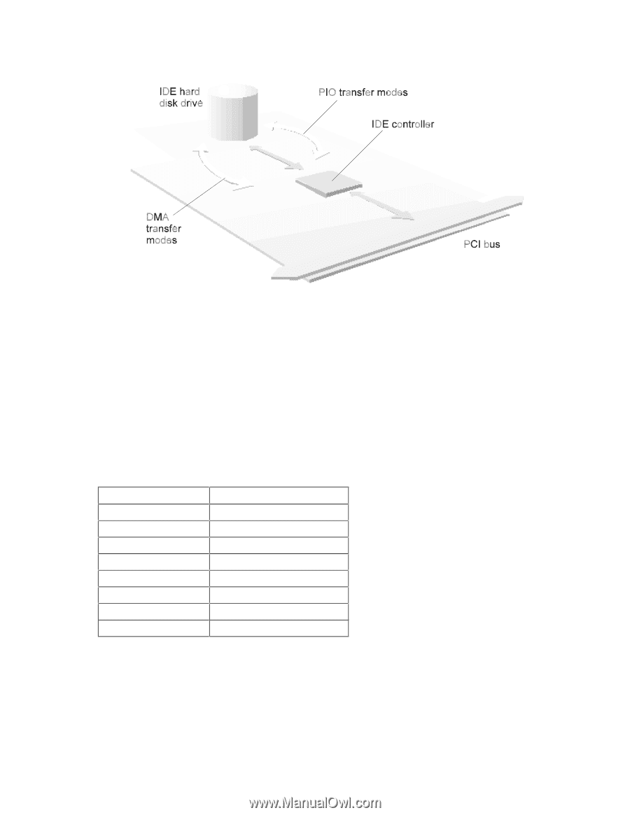
The IDE controller transfers data to or from IDE devices in response to data transfers received or requested on your PC's PCI bus. The technique used for a particular data transfer with an IDE device is chosen according to the type of transfer received or requested on the PCI bus. In this way, the IDE controller ensures that data transfers are optimized between the PCI bus and the IDE device. Your PC's IDE controller supports five PIO modes, PIO Mode 0 - 4, and three DMA modes, DMA Mode 0 - 2. Higher numbered modes offer increased data transfer rates than lower numbered modes. Not all IDE devices support all of these modes. When transferring data with an IDE device, the integrated IDE controller will select the highest numbered mode supported by the IDE device. Data transfer rates for all of these modes are given in the table below. Transfer Mode PIO Mode 0 PIO Mode 1 PIO Mode 2 PIO Mode 3 PIO Mode 4 DMA Mode 0 DMA Mode 1 DMA Mode 2 Maximum Transfer Rate 3.33 MB per second 5.22 MB per second 8.33 MB per second 11.1 MB per second 16.7 MB per second 4.2 MB per second 13.3 MB per second 16.7 MB per second PCI Master Capability The integrated IDE controller transfers data with your PC's processor and memory through the PCI bus. PCI devices fall into two categories: slaves and masters. A PCI slave is a device that can only respond to transfers or requests made by another PCI device - it cannot initiate transfers. A PCI master is able to initiate transfers and to take control of the PCI bus while a transfer is being made.
-
 1
1 -
2
-
3
-
4
-
5
-
6
-
7
-
8
-
9
-
10
-
11
-
12
-
13
-
14
-
15
-
16
-
17
-
18
-
 19
19 -
 20
20 -
 21
21 -
 22
22 -
 23
23 -
 24
24 -
 25
25 -
 26
26 -
 27
27 -
 28
28 -
 29
29 -
30
-
31
-
32
-
33
-
34
-
35
-
36
-
37
-
38
-
39
-
40
-
41
-
42
-
43
-
44
-
45
-
46
 |
 |