| Section |
Page |
| technical reference |
1 |
| technical reference |
1 |
| technical reference |
1 |
| hp workstation x1000 |
1 |
| Manufacturing Part Number:� n.a. |
1 |
| Edition E1001 |
1 |
| © Copyright 2001 |
1 |
| © Copyright 2001 |
1 |
| Hewlett-Packard Company |
1 |
| Legal Notices |
2 |
| Legal Notices |
2 |
| Hewlett-Packard Co. |
3 |
| Hewlett-Packard Co. |
3 |
| Technical Computer Division |
3 |
| 3404 E. Harmony Rd. Fort Collins, CO 80525 |
3 |
| preface |
13 |
| preface |
13 |
| important warnings |
13 |
| important warnings |
13 |
| avoid electrical shocks |
13 |
| avoid electrical shocks |
13 |
| WARNING To avoid electrical shock, do not open the power supply. There are no user-serviceable pa... |
13 |
| electrical |
13 |
| electrical |
13 |
| WARNING For your safety always connect the equipment to a grounded wall outlet. Always use a powe... |
13 |
| multimedia models |
13 |
| multimedia models |
13 |
| WARNING If your PC is a multimedia model, or if you have installed a sound card in your PC, alway... |
13 |
| removing and replacing the cover |
14 |
| removing and replacing the cover |
14 |
| WARNING For your safety, never remove the PC cover without first disconnecting the power cord fro... |
14 |
| safety information |
14 |
| safety information |
14 |
| WARNING There is a danger of explosion if the battery is incorrectly installed. For your safety, ... |
14 |
| static electricity |
15 |
| static electricity |
15 |
| CAUTION Static electricity can damage electronic components. Turn OFF all equipment. Don’t let yo... |
15 |
| workstation documentation roadmap |
15 |
| workstation documentation roadmap |
15 |
| <TABLE> |
15 |
| Table�1 |
15 |
| <TABLE HEADING> |
15 |
| <TABLE ROW> |
15 |
| If you want to... |
15 |
| Go to this source... |
15 |
| And refer to... |
15 |
| <TABLE BODY> |
15 |
| <TABLE ROW> |
15 |
| Find Information |
15 |
| Your computer |
15 |
| Start >Programs > HP Info > Finding Information |
15 |
| <TABLE ROW> |
15 |
| Set up your computer |
15 |
| Getting Started Guide |
15 |
| Chapter 1 “Setting Up and Using Your Workstation.” |
15 |
| <TABLE ROW> |
15 |
| Learn how to use your operating system |
15 |
| Your computer |
15 |
| Operating System Online Help |
15 |
| <TABLE ROW> |
15 |
| Learn how to upgrade your computer by installing accessories |
15 |
| This Technical Reference Manual |
15 |
| Chapter 6 “Removing and Replacing Hardware Parts” |
15 |
| <TABLE ROW> |
15 |
| Find out about the different support options available |
15 |
| www.hp.com/workst ations/support |
15 |
| The support options section |
15 |
| <TABLE ROW> |
15 |
| Find out how to troubleshoot your PC Workstation |
15 |
| This Technical Reference Manual |
15 |
| Chapter 7 “Troubleshooting Your Workstation” |
15 |
| technical information |
16 |
| technical information |
16 |
| <TABLE> |
16 |
| <TABLE BODY> |
16 |
| <TABLE ROW> |
16 |
| Characteristics |
16 |
| HP Workstation x1000 |
16 |
| <TABLE ROW> |
16 |
| Weight (configuration with one CD-ROM drive, excluding keyboard and display) |
16 |
| 14.3 kg (31.5 pounds) |
16 |
| <TABLE ROW> |
16 |
| Dimensions |
16 |
| Width: �20.6cm (8.1in.) Height: 47.5cm (18.7in.) Depth: 44.2cm (17.4in.) |
16 |
| <TABLE ROW> |
16 |
| Footprint |
16 |
| 0.09 m2 (0.98 sq ft). |
16 |
| <TABLE ROW> |
16 |
| Acoustic noise emission (ISO�7779) |
16 |
| Sound power level |
16 |
| <TABLE ROW> |
16 |
| Power Supply |
16 |
| 100 - 127 VAC, 7.0 A rms |
16 |
| <TABLE ROW> |
16 |
| Storage Humidity |
16 |
| 8% to 85% (relative) |
16 |
| <TABLE ROW> |
16 |
| Operating Temperature |
16 |
| +10 �C to +35 �C (+50 �F to +95�F). |
16 |
| 1 system overview |
17 |
| 1 system overview |
17 |
| • Introduces the system’s internal and external features |
17 |
| • Introduces the system’s internal and external features |
17 |
| • Lists the system’s specifications and characteristic data |
17 |
| • Provides a summary of the available documentation |
17 |
| workstation description |
18 |
| workstation description |
18 |
| <TABLE> |
18 |
| <TABLE HEADING> |
18 |
| <TABLE ROW> |
18 |
| Feature |
18 |
| Description |
18 |
| <TABLE BODY> |
18 |
| <TABLE ROW> |
18 |
| System Board |
18 |
| System Board |
18 |
| Dimensions: 9.5in. ¥ 9.5 in. in an Extended-ATX (E-ATX) package |
18 |
| <TABLE ROW> |
18 |
| Processor |
18 |
| Processor |
18 |
| Intel Pentium�4 processor |
18 |
| <TABLE ROW> |
18 |
| Cache Memory (integrated in processor package) |
18 |
| Cache Memory (integrated in processor package) |
18 |
| • Level 1: 12KB code, 8KB data |
18 |
| • Level 1: 12KB code, 8KB data |
18 |
| • Level 1: 12KB code, 8KB data |
18 |
| • Level 2: 256KB |
18 |
| <TABLE ROW> |
18 |
| Internal Processor Clock Speed |
18 |
| Internal Processor Clock Speed |
18 |
| 1.7GHz, 1.9GHz, and 2.0 GHz |
18 |
| <TABLE ROW> |
18 |
| Chipset |
18 |
| Chipset |
18 |
| Intel�i845 chipset, including Memory Controller Hub (MCH) Host Bridge, Input/Output Controller Hu... |
18 |
| <TABLE ROW> |
18 |
| Basic I/O System (BIOS) |
18 |
| Basic I/O System (BIOS) |
18 |
| Based on American Megatrends core, including: |
18 |
| • 4 megabits of flash memory |
18 |
| • 4 megabits of flash memory |
18 |
| • Support for PCI 2.2 specification |
18 |
| • Support for DIMM memory modules |
18 |
| <TABLE ROW> |
18 |
| Firmware - BIOS |
18 |
| Firmware - BIOS |
18 |
| Flash EEPROM: Intel’s firmware hub concept |
18 |
| <TABLE ROW> |
18 |
| Operating System |
18 |
| Operating System |
18 |
| All models come preloaded with Windows 2000 |
18 |
| <TABLE ROW> |
18 |
| Main Memory |
18 |
| Main Memory |
18 |
| Three DIMM sockets that support 128MB and 256MB SDRAM memory modules. |
18 |
| <TABLE ROW> |
19 |
| Mass Storage |
19 |
| Mass Storage |
19 |
| Six shelves, supporting:� |
19 |
| • One front-access, third-height 3 1/2-inch drive (for the flexible disk drive) (1-inch height) |
19 |
| • One front-access, third-height 3 1/2-inch drive (for the flexible disk drive) (1-inch height) |
19 |
| • Three front-access, half-height, 5 1/4-inch drives (1-inch height). |
19 |
| • Two internal 3 1/2-inch hard disk drives (1-inch height) |
19 |
| <TABLE ROW> |
19 |
| SCSI Controller |
19 |
| SCSI Controller |
19 |
| Adaptec Ultra 160 SCSI PCI card. |
19 |
| <TABLE ROW> |
19 |
| IDE Controller |
19 |
| IDE Controller |
19 |
| All models include an integrated Ultra ATA-100 capable controller that supports as many as four I... |
19 |
| <TABLE ROW> |
19 |
| Graphics Controllers |
19 |
| Graphics Controllers |
19 |
| • nVIDIA Quadro2 MXR with TwinView or nVIDIA Quadro2 Pro |
19 |
| • nVIDIA Quadro2 MXR with TwinView or nVIDIA Quadro2 Pro |
19 |
| • nVIDIA Quadro2 MXR with TwinView or nVIDIA Quadro2 Pro |
19 |
| • Matrox Millennium G450-Dual monitor AGP graphics controller with 16MB DDR graphics memory (maxi... |
19 |
| <TABLE ROW> |
19 |
| Accessory Card Slots |
19 |
| Accessory Card Slots |
19 |
| One AGP Universal 4X 32-bit slot supporting 1.5V AGP cards (£25W). |
19 |
| <TABLE ROW> |
19 |
| <TABLE ROW> |
19 |
| LAN (internal) |
19 |
| LAN (internal) |
19 |
| All models come with an internal 10/100TX LAN connector. |
19 |
| <TABLE ROW> |
19 |
| CD-ROM Drive |
19 |
| CD-ROM Drive |
19 |
| Models include either an IDE 48X CD-ROM, CD-RW drive, or DVD drive. |
19 |
| <TABLE ROW> |
19 |
| Audio |
19 |
| Audio |
19 |
| Internal speaker attached to the workstation’s chassis and connected by cable to the system board. |
19 |
| <TABLE ROW> |
20 |
| System Board Connectors |
20 |
| System Board Connectors |
20 |
| • One flexible disk drive connector |
20 |
| • One flexible disk drive connector |
20 |
| • One flexible disk drive connector |
20 |
| • Two ATA-100 capable IDE connectors (they each support up to two IDE devices) |
20 |
| • One CD-IN audio connector |
20 |
| • Internal speaker connector |
20 |
| • Battery socket |
20 |
| • Status panel connector |
20 |
| • Main power supply connector and ATX 12V power connector |
20 |
| • Main chassis fan connector |
20 |
| • Processor fan connector |
20 |
| • Chassis intrusion connector |
20 |
| <TABLE ROW> |
20 |
| Rear Connectors (color coded) |
20 |
| Rear Connectors (color coded) |
20 |
| • Keyboard/Mouse |
20 |
| • Keyboard/Mouse |
20 |
| • Keyboard/Mouse |
20 |
| — HP multi-media keyboard with PS/2 connector |
20 |
| — HP multi-media keyboard with PS/2 connector |
20 |
| — HP enhanced scrolling mouse with PS/2 connector |
20 |
| • 25-pin parallel |
20 |
| — Mode: Centronics or bidirectional modes (ECP/EPP) |
20 |
| — Mode: Centronics or bidirectional modes (ECP/EPP) |
20 |
| — Parallel port: 1 (378h, IRQ 7), 2 (278h, IRQ 5), or Off |
20 |
| • 9-pin serial (two, buffered) |
20 |
| — Standard: Two UART 16550 buffered serial ports (both RS-232-C). |
20 |
| — Standard: Two UART 16550 buffered serial ports (both RS-232-C). |
20 |
| — Serial Ports A and B: 2F8h (IRQ 3), 2E8h (IRQ 3), 3F8h (IRQ 4), 3E8h (IRQ 4), or Off |
20 |
| • Dual USB connectors |
20 |
| • Audio |
20 |
| — LINE IN jack (3.5mm) |
20 |
| — LINE IN jack (3.5mm) |
20 |
| — LINE OUT jack (3.5mm) |
20 |
| — MIC IN jack (3.5mm) |
20 |
| • 10/100TX LAN |
20 |
| <TABLE ROW> |
20 |
| Front Connectors |
20 |
| Front Connectors |
20 |
| • Dual USB connectors |
20 |
| • Dual USB connectors |
20 |
| • Dual USB connectors |
20 |
| • Firewire connector (optionally enabled; see Chapter 5) |
20 |
| packaging |
21 |
| packaging |
21 |
| Figure 1�1 |
21 |
| Figure�1�1 Workstation |
21 |
| Figure�1�1 Workstation |
21 |
| <GRAPHIC> |
22 |
| Figure�1�2 Location of Rear Panel Connectors |
22 |
| <GRAPHIC> |
23 |
| internal features |
23 |
| • Memory Controller Hub (MCH) |
23 |
| • Memory Controller Hub (MCH) |
23 |
| • Input/Output Controller Hub (ICH) |
23 |
| • Host bus |
23 |
| <TABLE> |
23 |
| <TABLE HEADING> |
23 |
| <TABLE ROW> |
23 |
| For information about... |
23 |
| Refer to the chapter... |
23 |
| <TABLE BODY> |
23 |
| <TABLE ROW> |
23 |
| System board components |
23 |
| system board |
23 |
| <TABLE ROW> |
23 |
| HP�BIOS routines |
23 |
| hp BIOS |
23 |
| <TABLE ROW> |
23 |
| Tests and error messages |
23 |
| tests and error messages |
23 |
| <TABLE ROW> |
23 |
| Graphics, network and SCSI devices, and mass storage devices |
23 |
| hardware components |
23 |
| <TABLE ROW> |
23 |
| Accessories Installation and Parts Replacement |
23 |
| removing and replacing hardware parts |
23 |
| <TABLE ROW> |
23 |
| Use or configuration problems |
23 |
| troubleshooting your workstation |
23 |
| <TABLE ROW> |
23 |
| Troubleshooting and Recovery |
23 |
| troubleshooting your workstation |
23 |
| <TABLE ROW> |
23 |
| Contacting support |
23 |
| troubleshooting your workstation |
23 |
| front panel |
24 |
| front panel |
24 |
| • The On/Off LED is green when the power is on, or the power button is pushed in. If the power is... |
24 |
| • The On/Off LED is green when the power is on, or the power button is pushed in. If the power is... |
24 |
| • The hard disk drive activity LED is orange during POST and hard disk drive access. When the sys... |
24 |
| • The hard disk drive activity LED is orange during POST and hard disk drive access. When the sys... |
24 |
| Figure�1�3 Front Panel |
24 |
| Figure�1�3 Front Panel |
24 |
| <GRAPHIC> |
25 |
| specifications and characteristics |
25 |
| physical characteristics |
25 |
| physical characteristics |
25 |
| <TABLE> |
25 |
| <TABLE BODY> |
25 |
| <TABLE ROW> |
25 |
| System Processing Unit |
25 |
| System Processing Unit |
25 |
| <TABLE ROW> |
25 |
| Weight: (Standard configuration as shipped, excluding keyboard and display) |
25 |
| 14.3 kilograms (31.5 pounds) |
25 |
| <TABLE ROW> |
25 |
| Dimensions |
25 |
| 44.2cm max. (D) ¥ 20.6cm (W) ¥ 47.5cm (H) (17.4 inches ¥ 8.1 inches ¥ 18.7 inches) |
25 |
| <TABLE ROW> |
25 |
| Footprint |
25 |
| 0.09 square meters (0.98 square feet) |
25 |
| electrical specifications |
26 |
| electrical specifications |
26 |
| <TABLE> |
26 |
| <TABLE HEADING> |
26 |
| <TABLE ROW> |
26 |
| Parameter |
26 |
| Total Rating |
26 |
| Peak (15 secs.) |
26 |
| Maximum per PCI Slots 32-bit |
26 |
| Maximum for AGP Slot |
26 |
| <TABLE ROW> |
26 |
| Standard Connector |
26 |
| <TABLE BODY> |
26 |
| <TABLE ROW> |
26 |
| Input voltage |
26 |
| 100-127 VAC |
26 |
| 200-250 �VAC |
26 |
| — |
26 |
| — |
26 |
| — |
26 |
| <TABLE ROW> |
26 |
| Input current (max) |
26 |
| 7.0 A |
26 |
| 3.5 A |
26 |
| — |
26 |
| — |
26 |
| — |
26 |
| <TABLE ROW> |
26 |
| Input frequency |
26 |
| 50 to 60 Hz |
26 |
| — |
26 |
| — |
26 |
| — |
26 |
| <TABLE ROW> |
26 |
| Available power |
26 |
| 250 W |
26 |
| — |
26 |
| 85W total for PCI slots and AGP slot |
26 |
| <TABLE ROW> |
26 |
| Max current at +12�V |
26 |
| 13 A |
26 |
| — |
26 |
| 0.5 A |
26 |
| 1 A |
26 |
| <TABLE ROW> |
26 |
| Max current at -12�V |
26 |
| –1.2 A |
26 |
| — |
26 |
| 0.1 A |
26 |
| — |
26 |
| <TABLE ROW> |
26 |
| Max current at +3.3V |
26 |
| 16 A |
26 |
| — |
26 |
| 7.6 A |
26 |
| 6 A |
26 |
| <TABLE ROW> |
26 |
| Max current at +5V |
26 |
| 25 A |
26 |
| 31 A |
26 |
| 5 A |
26 |
| 2 A |
26 |
| <TABLE ROW> |
26 |
| Max current at -5V |
26 |
| 0.3 A |
26 |
| — |
26 |
| — |
26 |
| — |
26 |
| <TABLE ROW> |
26 |
| Max current at +5V stdby |
26 |
| 2 A |
26 |
| — |
26 |
| — |
26 |
| 1. Disconnect the power cord. |
26 |
| 1. Disconnect the power cord. |
26 |
| 2. Determine what caused the overload, and fix the problem. |
26 |
| 3. Reconnect the power cord, and reboot the workstation. |
26 |
| power consumption and cooling |
27 |
| power consumption and cooling |
27 |
| <TABLE> |
27 |
| <TABLE BODY> |
27 |
| <TABLE ROW> |
27 |
| Additional Component |
27 |
| Additional Component |
27 |
| <TABLE ROW> |
27 |
| • Processor |
27 |
| • Processor |
27 |
| • Processor |
27 |
| • SCSI hard disk drive with I/O access |
27 |
| • SCSI hard disk without I/O access (idle) |
27 |
| • PCI card |
27 |
| 50W 23W � ����� 16W ��������10W to 25W� |
27 |
| - 170.6Btu/h - 78.4Btu/h - 54.5Btu/h - 64.1Btu/h to 122.8Btu/h |
27 |
| environmental specifications |
28 |
| environmental specifications |
28 |
| <TABLE> |
28 |
| <TABLE BODY> |
28 |
| <TABLE ROW> |
28 |
| Environmental Specifications (System Processing Unit with Hard Disk) |
28 |
| Environmental Specifications (System Processing Unit with Hard Disk) |
28 |
| <TABLE ROW> |
28 |
| Operating Temperature |
28 |
| +10 �C to +35 �C (+50 �F to +95 �F). |
28 |
| <TABLE ROW> |
28 |
| Storage Temperature |
28 |
| -40 �C to +70�C (-40 �F to +158 �F). |
28 |
| <TABLE ROW> |
28 |
| Over-Temperature Shutdown |
28 |
| +50�C (+122�F) |
28 |
| <TABLE ROW> |
28 |
| Operating Humidity |
28 |
| 15% to 80% (relative). |
28 |
| <TABLE ROW> |
28 |
| Storage Humidity |
28 |
| 8% to 85% (relative).1 |
28 |
| <TABLE ROW> |
28 |
| Acoustic noise emission (ISO 7779): |
28 |
| • Idle |
28 |
| • Idle |
28 |
| • Operating with hard disk access |
28 |
| ���Sound Power |
28 |
| ���Sound Power |
28 |
| LwA <= 4.6 BA |
28 |
| LwA <= 4.6 BA |
28 |
| LwA <= 5.3 BA |
28 |
| <TABLE ROW> |
28 |
| Operating Altitude |
28 |
| 10,000ft (3048m) max |
28 |
| <TABLE ROW> |
28 |
| Storage Altitude |
28 |
| 15,000ft (4600m) max |
28 |
| power saving and ergonometry |
29 |
| power saving and ergonometry |
29 |
| • No sleeping state: Windows NT 4.0 (Full On and Off). |
29 |
| • No sleeping state: Windows NT 4.0 (Full On and Off). |
29 |
| • ACPI: Windows 2000 (Full On, Standby, Hibernate, Off). |
29 |
| <TABLE> |
29 |
| <TABLE BODY> |
29 |
| <TABLE ROW> |
29 |
| Windows 2000 |
29 |
| Windows 2000 |
29 |
| Windows NT 4.0 |
29 |
| Windows NT 4.0 |
29 |
| <TABLE ROW> |
29 |
| A P M |
29 |
| A |
29 |
| P |
29 |
| M |
29 |
| Full On |
29 |
| Full On |
29 |
| Not Supported by Windows 2000 |
29 |
| Supported |
29 |
| <TABLE ROW> |
29 |
| Suspend |
29 |
| Suspend |
29 |
| Not Supported by Windows NT 4.0 |
29 |
| <TABLE ROW> |
29 |
| Off |
29 |
| Off |
29 |
| Supported |
29 |
| <TABLE ROW> |
29 |
| A C P I |
29 |
| A |
29 |
| C |
29 |
| P |
29 |
| I |
29 |
| Standby (S1 or S3) |
29 |
| Standby (S1 or S3) |
29 |
| Supported (implemented as S3, Suspend to RAM) |
29 |
| APM only Operating System |
29 |
| <TABLE ROW> |
29 |
| Hibernate (S4) |
29 |
| Hibernate (S4) |
29 |
| Supported |
29 |
| <TABLE ROW> |
29 |
| Off (S5) |
29 |
| Off (S5) |
29 |
| Supported |
29 |
| power saving and ergonometry for APM systems |
30 |
| power saving and ergonometry for APM systems |
30 |
| <TABLE> |
30 |
| <TABLE HEADING> |
30 |
| <TABLE ROW> |
30 |
| Full On |
30 |
| Suspend |
30 |
| Off |
30 |
| <TABLE BODY> |
30 |
| <TABLE ROW> |
30 |
| Processor |
30 |
| Processor |
30 |
| Normal speed |
30 |
| Halted |
30 |
| Halted |
30 |
| <TABLE ROW> |
30 |
| Display |
30 |
| Display |
30 |
| On |
30 |
| — |
30 |
| — |
30 |
| <TABLE ROW> |
30 |
| Hard disk drive |
30 |
| Hard disk drive |
30 |
| Normal speed |
30 |
| Halted |
30 |
| Halted |
30 |
| <TABLE ROW> |
30 |
| Power consumption |
30 |
| Power consumption |
30 |
| 250W |
30 |
| — |
30 |
| — |
30 |
| <TABLE ROW> |
30 |
| Resume events |
30 |
| Resume events |
30 |
| Keyboard, network (RWU), modem, USB |
30 |
| Space bar or power button, RPO |
30 |
| <TABLE ROW> |
30 |
| Resume delay |
30 |
| Resume delay |
30 |
| A few seconds |
30 |
| Boot delay |
30 |
| power saving modes/resume events for ACPI systems |
31 |
| power saving modes/resume events for ACPI systems |
31 |
| <TABLE> |
31 |
| <TABLE HEADING> |
31 |
| <TABLE ROW> |
31 |
| Full On (S0) |
31 |
| Suspend (S1) |
31 |
| Suspend to RAM (S3) |
31 |
| Suspend to Disk (S4) |
31 |
| Off (S5) |
31 |
| <TABLE BODY> |
31 |
| <TABLE ROW> |
31 |
| Processor |
31 |
| Processor |
31 |
| Normal speed |
31 |
| Halted |
31 |
| Off |
31 |
| Off |
31 |
| Off |
31 |
| <TABLE ROW> |
31 |
| Display |
31 |
| Display |
31 |
| On |
31 |
| Blanked |
31 |
| Off |
31 |
| Off |
31 |
| Off |
31 |
| <TABLE ROW> |
31 |
| Hard Disk Drive |
31 |
| Hard Disk Drive |
31 |
| Normal speed |
31 |
| Halted |
31 |
| Off |
31 |
| Off |
31 |
| Off |
31 |
| <TABLE ROW> |
31 |
| Active Power Planes |
31 |
| Active Power Planes |
31 |
| VCC VCCAux |
31 |
| VCC VCCAux |
31 |
| Memory VCCAux |
31 |
| VCCAux |
31 |
| VCCAux |
31 |
| <TABLE ROW> |
31 |
| Power Consumption |
31 |
| Power Consumption |
31 |
| 250W |
31 |
| — |
31 |
| — |
31 |
| — |
31 |
| — |
31 |
| <TABLE ROW> |
31 |
| Resume Events |
31 |
| Resume Events |
31 |
| Power button, LAN, Modem, USB, Scheduler, HP Start Key |
31 |
| Power button, LAN, Modem, Scheduler, HP Start Key |
31 |
| Power button, LAN, Modem, Scheduler, HP Start Key |
31 |
| Power button, HP Start Key |
31 |
| <TABLE ROW> |
31 |
| Resume Delay |
31 |
| Resume Delay |
31 |
| Instantaneous |
31 |
| Instantaneous |
31 |
| BIOS boot delay |
31 |
| Regular boot delay |
31 |
| power-on from space-bar |
32 |
| power-on from space-bar |
32 |
| • the computer is connected to a Power-On keyboard (recognizable by a Power-On icon on the space ... |
32 |
| • the computer is connected to a Power-On keyboard (recognizable by a Power-On icon on the space ... |
32 |
| • the function hasn’t been disabled by setting switch 6 to |
32 |
| soft power down |
32 |
| soft power down |
32 |
| documentation |
33 |
| documentation |
33 |
| access hp world wide web site |
33 |
| access hp world wide web site |
33 |
| ���http://www.hp.com/workstations/support |
33 |
| where to find the information |
33 |
| where to find the information |
33 |
| 2 system board |
37 |
| 2 system board |
37 |
| • Memory Controller Hub (MCH) |
37 |
| • Memory Controller Hub (MCH) |
37 |
| • Input/Output Controller Hub (ICH2) |
37 |
| • FirmWare Hub (FWH) |
37 |
| • System Bus |
37 |
| system board description |
38 |
| system board description |
38 |
| Figure 2�1 |
38 |
| Figure�2�1 System Board Dimensions |
38 |
| Figure�2�1 System Board Dimensions |
38 |
| <GRAPHIC> |
39 |
| Figure�2�2 System Board Chips and Connectors |
39 |
| Figure�2�2 System Board Chips and Connectors |
39 |
| <GRAPHIC> |
40 |
| architectural view for the x1000 workstation |
40 |
| <GRAPHIC> |
41 |
| accessory board slots |
41 |
| Figure 2�3 |
41 |
| Figure�2�3 Accessory Board Slots |
41 |
| Figure�2�3 Accessory Board Slots |
41 |
| <GRAPHIC> |
41 |
| accelerated graphics port slot |
41 |
| Figure�2�4 AGP Slot |
41 |
| Figure�2�4 AGP Slot |
41 |
| <GRAPHIC> |
42 |
| peripheral component interconnect slots |
43 |
| peripheral component interconnect slots |
43 |
| Figure�2�5 PCI Slots |
43 |
| Figure�2�5 PCI Slots |
43 |
| <GRAPHIC> |
43 |
| • 7W maximum PCI board in the PCI slot |
43 |
| • 15W maximum PCI board in the PCI slot |
43 |
| • 25W� maximum PCI board in the PCI slot |
43 |
| <TABLE> |
44 |
| <TABLE BODY> |
44 |
| <TABLE ROW> |
44 |
| PCI Card |
44 |
| PCI Card |
44 |
| <TABLE ROW> |
44 |
| 3.3V and 5V |
44 |
| 3.3V and 5V |
44 |
| Universal (3.3V or 5V compatible) |
44 |
| Universal (3.3V or 5V compatible) |
44 |
| <TABLE ROW> |
44 |
| PCI Slot |
44 |
| PCI Slot |
44 |
| 32-bit/ 33MHz |
44 |
| 64-bit/ 33MHz |
44 |
| 32-bit/ 33MHz or 66MHz |
44 |
| 64-bit/ 33MHz or 66MHz |
44 |
| <TABLE ROW> |
44 |
| Slots 1, 2, and 3 5V, 32-bit/33MHz |
44 |
| Slots 1, 2, and 3 5V, 32-bit/33MHz |
44 |
| yes |
44 |
| yes |
44 |
| yes |
44 |
| yes |
44 |
| yes |
44 |
| yes |
44 |
| system board switches |
45 |
| system board switches |
45 |
| Figure�2�6 System Board Switches |
45 |
| Figure�2�6 System Board Switches |
45 |
| <GRAPHIC> |
45 |
| <TABLE HEADING> |
45 |
| <TABLE ROW> |
45 |
| Switch |
45 |
| Default Position |
45 |
| Use |
45 |
| <TABLE BODY> |
45 |
| <TABLE ROW> |
45 |
| 1-4 |
45 |
| OFF |
45 |
| Reserved. Do not change default�settings. |
45 |
| <TABLE ROW> |
45 |
| 5 |
45 |
| OFF |
45 |
| Clear CMOS |
45 |
| <TABLE ROW> |
45 |
| 6 |
45 |
| OFF |
45 |
| Clear password |
45 |
| <TABLE ROW> |
45 |
| 7 |
45 |
| OFF |
45 |
| BIOS recovery. ON enables the BIOS recovery mode at next boot. |
45 |
| <TABLE ROW> |
45 |
| 8 |
45 |
| OFF |
45 |
| Reserved. Do not change default settings. |
45 |
| <TABLE ROW> |
45 |
| 9 |
45 |
| OFF |
45 |
| Hardware flash protection. Must be set to ON before any flashing. |
45 |
| <TABLE ROW> |
45 |
| 10 |
45 |
| OFF |
45 |
| Reserved. Do not change default�settings. |
45 |
| chipset |
46 |
| chipset |
46 |
| • The 82845 MCH is a bridge between the: |
46 |
| • The 82845 MCH is a bridge between the: |
46 |
| — System bus |
46 |
| — System bus |
46 |
| — SDRAM bus (main memory) |
46 |
| — AGP 4x (graphic) bus |
46 |
| — Hub link 8-bit |
46 |
| • The 82801BA ICH2 is a bridge between the 32-bit, 33MHz PCI bus and the SMBus. Additionally, the... |
46 |
| — Integrated IDE controller (Ultra ATA/100 capable) |
46 |
| — Integrated IDE controller (Ultra ATA/100 capable) |
46 |
| — Upstream Hub Interface for access to the MCH |
46 |
| — USB controller |
46 |
| — SMBus controller |
46 |
| — Low Pin Count (LPC) interface |
46 |
| — FWH interface |
46 |
| — ACPI Power Management Logic |
46 |
| — AC’97 2.1 Compliant Link |
46 |
| — PCI Interface |
46 |
| — Integrated System Management Controller |
46 |
| — Alert-On-LAN (AOL) |
46 |
| — Integrated LAN Controller |
46 |
| • The Firmware Hub (FWH) stores system BIOS and SCSI BIOS (i.e., the nonvolatile memory component... |
46 |
| memory controller hub (82845) |
47 |
| memory controller hub (82845) |
47 |
| Figure�2�7 MCH Chip Location |
47 |
| Figure�2�7 MCH Chip Location |
47 |
| <GRAPHIC> |
48 |
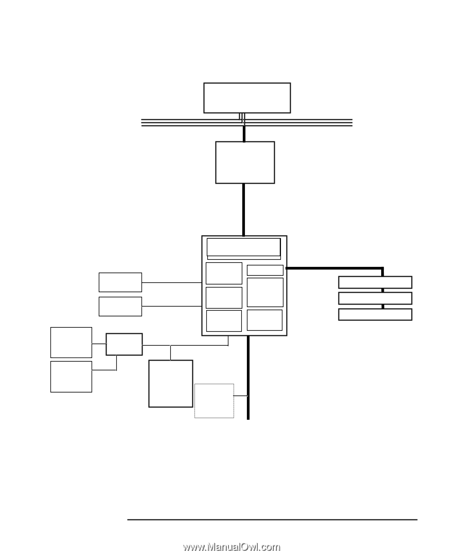
| Figure�2�8 System Block Diagram using MCH |
48 |
| Figure�2�8 System Block Diagram using MCH |
48 |
| <GRAPHIC> |
49 |
| <TABLE HEADING> |
49 |
| <TABLE ROW> |
49 |
| Feature |
49 |
| Feature |
49 |
| <TABLE BODY> |
49 |
| <TABLE ROW> |
49 |
| • Processor/system bus: |
49 |
| • Processor/system bus: |
49 |
| • Processor/system bus: |
49 |
| — Supports a 400MHz system bus |
49 |
| — Supports a 400MHz system bus |
49 |
| — Provides an twelve-deep In-Order Queue that supports as many as eight outstanding transaction r... |
49 |
| — Desktop optimized AGTL+ bus driver technology with integrated AGTL + termination resistors |
49 |
| — Support for 32-bit system bus address |
49 |
| • Accelerated Graphics Port (AGP) interface: |
49 |
| • Accelerated Graphics Port (AGP) interface: |
49 |
| • Accelerated Graphics Port (AGP) interface: |
49 |
| — Single 1.5V AGP connector |
49 |
| — Single 1.5V AGP connector |
49 |
| — AGP 2.0 compliant, including AGP 4x data transfers and 2x/4x Fast Write protocol |
49 |
| — AGP 1.5V connector support with 1.5V signalling only |
49 |
| — AGP PIPE# or SBA initiated accesses to DRAM is not snooped |
49 |
| — AGP FRAME initiated accesses to DRAM are snooped (snooper identifies that data is coherent in c... |
49 |
| — Hierarchical PCI configuration mechanism |
49 |
| — Delayed transaction support for AGP-to-DRAM reads that cannot be serviced immediately |
49 |
| <TABLE ROW> |
49 |
| • Memory Controller |
49 |
| • Memory Controller |
49 |
| • Memory Controller |
49 |
| <TABLE ROW> |
49 |
| — Single Channel SDRAM bus |
49 |
| — Single Channel SDRAM bus |
49 |
| — Single Channel SDRAM bus |
49 |
| — SDRAM 128Mbit and 256Mbit devices |
49 |
| — Supports up to three double sided DIMMs (6 device rows) |
49 |
| — All supported devices must have four banks |
49 |
| — Supports page sizes of 2KB, 4KB, 8KB and 16KB. Page size is individually selected for every row. |
49 |
| — Maximum DRAM address decode space of 4GB |
49 |
| — 128MB to 384MB using 128Mb technology; up to 768MB using 256Mb technology; the 512Mb technology... |
49 |
| — ECC DIMM support |
49 |
| — ECC DIMM support |
49 |
| — ECC DIMM support |
49 |
| — 133MHz SDRAM interface |
49 |
| — 64-bit data interface |
49 |
| — Supports only 3.3V DIMM DRAM configuration |
49 |
| — No registered DIMM support |
49 |
| — Support for Symmetrical and Asymmetrical DRAM addressing |
49 |
| — Refresh Mechanism: CAS-before-RAS only |
49 |
| — Support for DIMM Serial Presence Detect (SPD) scheme via SMBus interface |
49 |
| — STR power management support via self refresh mode using CKE |
49 |
| <TABLE ROW> |
50 |
| • Hub Link 8-bit interface to ICH2: |
50 |
| • Hub Link 8-bit interface to ICH2: |
50 |
| • Hub Link 8-bit interface to ICH2: |
50 |
| — High-speed interconnect between the MCH and ICH2 (266MB/sec) |
50 |
| — High-speed interconnect between the MCH and ICH2 (266MB/sec) |
50 |
| — |
50 |
| <TABLE ROW> |
50 |
| • Power management: |
50 |
| • Power management: |
50 |
| • Power management: |
50 |
| — SMRAM space remapping to A0000h - BFFFFh (128KB). |
50 |
| — SMRAM space remapping to A0000h - BFFFFh (128KB). |
50 |
| — Extended SMRAM space above 256MB, additional 128KB, 256KB, 512KB, 1MB TSEG from top of memory, ... |
50 |
| — ACPI 1.0 compliant power management |
50 |
| — APM 1.2 compliant power management |
50 |
| • Arbitration: |
50 |
| • Arbitration: |
50 |
| • Arbitration: |
50 |
| — Distributed arbitration model for concurrency support |
50 |
| — Distributed arbitration model for concurrency support |
50 |
| — Concurrent operations of system, hub interface, AGP, and memory buses supported through a dedic... |
50 |
| <TABLE ROW> |
50 |
| • 593 FC-BGA MCH package |
50 |
| • 593 FC-BGA MCH package |
50 |
| • 593 FC-BGA MCH package |
50 |
| • I/O device support: |
50 |
| • I/O device support: |
50 |
| • I/O device support: |
50 |
| — I/O Controller Hub (ICH2) |
50 |
| — I/O Controller Hub (ICH2) |
50 |
| MCH overview |
51 |
| MCH overview |
51 |
| accelerated graphics port (AGP) bus interface |
51 |
| accelerated graphics port (AGP) bus interface |
51 |
| hub interface |
52 |
| hub interface |
52 |
| SDRAM interface |
52 |
| SDRAM interface |
52 |
| DIMM memory slots |
53 |
| DIMM memory slots |
53 |
| • DIMM1 |
53 |
| • DIMM1 |
53 |
| • DIMM2 |
53 |
| • DIMM3 |
53 |
| Figure�2�9 DIMM Memory Slot |
53 |
| Figure�2�9 DIMM Memory Slot |
53 |
| <GRAPHIC> |
53 |
| read/write buffers |
53 |
| read/write buffers |
53 |
| system clocking |
54 |
| system clocking |
54 |
| the input/output controller hub 2 (82801BA) |
55 |
| the input/output controller hub 2 (82801BA) |
55 |
| Figure�2�10 Input/Output Controller Hub 2 Chip |
55 |
| Figure�2�10 Input/Output Controller Hub 2 Chip |
55 |
| <GRAPHIC> |
56 |
| Figure�2�11 System Block Diagram Using ICH2 |
56 |
| <GRAPHIC> |
57 |
| <TABLE HEADING> |
57 |
| <TABLE ROW> |
57 |
| Feature |
57 |
| Feature |
57 |
| <TABLE BODY> |
57 |
| <TABLE ROW> |
57 |
| • Multifunction PCI bus interface: |
57 |
| • Multifunction PCI bus interface: |
57 |
| • Multifunction PCI bus interface: |
57 |
| — PCI at 32-bit 33MHz |
57 |
| — PCI at 32-bit 33MHz |
57 |
| — PCI 2.2 specification |
57 |
| — 133MB/sec data transfer rate |
57 |
| — Master PCI device support for as many as three devices |
57 |
| • Enhanced DMA controller: |
57 |
| • Enhanced DMA controller: |
57 |
| • Enhanced DMA controller: |
57 |
| — Two 82C37 DMA controllers |
57 |
| — Two 82C37 DMA controllers |
57 |
| — PCI DMA with two PC/PCI channels in pairs |
57 |
| — LPC DMA |
57 |
| — DMA collection buffer to provide Type-F DMA performance for all DMA channels |
57 |
| <TABLE ROW> |
57 |
| • USB, supporting: |
57 |
| • USB, supporting: |
57 |
| • USB, supporting: |
57 |
| — USB 1.1 compliant |
57 |
| — USB 1.1 compliant |
57 |
| — UHCI implementation with four USB ports for serial transfers at 1.2 or 1.5Mbit/sec |
57 |
| — Wake-up from sleeping states |
57 |
| — Legacy keyboard/mouse software |
57 |
| • Interrupt Controller: |
57 |
| • Interrupt Controller: |
57 |
| • Interrupt Controller: |
57 |
| — Two cascaded 82C59 controllers |
57 |
| — Two cascaded 82C59 controllers |
57 |
| — Integrated I/O APIC capability |
57 |
| — 15 interrupt support in 8259 mode, 24 supported in I/O APIC mode |
57 |
| — Serial interrupt protocol |
57 |
| <TABLE ROW> |
57 |
| • Power Management Logic: |
57 |
| • Power Management Logic: |
57 |
| • Power Management Logic: |
57 |
| — ACPI 1.0 compliant |
57 |
| — ACPI 1.0 compliant |
57 |
| — Support for APM-based legacy power management for non-ACPI implementations |
57 |
| — ACPI defined power states (S1, S3, S4, S5) |
57 |
| — ACPI power management timer |
57 |
| — SMI generation |
57 |
| — All registers readable/restorable for proper resume from 0V suspend states |
57 |
| — PCI PME# |
57 |
| • Integrated IDE controller: |
57 |
| • Integrated IDE controller: |
57 |
| • Integrated IDE controller: |
57 |
| — Independent timing of as many as four drives |
57 |
| — Independent timing of as many as four drives |
57 |
| — Ultra ATA/100 mode (100MB/sec) |
57 |
| — Ultra ATA/66 mode (66MB/sec) |
57 |
| — Ultra ATA/33 mode (33MB/sec) |
57 |
| — PIO mode four transfers as fast as 14MB/sec |
57 |
| — Separate IDE connections for primary and secondary cables |
57 |
| — Integrated 16 x 32-bit buffer for IDE PCI burst transfers |
57 |
| — Write ping-pong buffer for faster write performances |
57 |
| <TABLE ROW> |
57 |
| • Real-time clock, supporting: |
57 |
| • Real-time clock, supporting: |
57 |
| • Real-time clock, supporting: |
57 |
| — 256-byte battery-backed CMOS RAM |
57 |
| — 256-byte battery-backed CMOS RAM |
57 |
| — Hardware implementation to indicate century rollover |
57 |
| • System TCO reduction circuits: |
57 |
| • System TCO reduction circuits: |
57 |
| • System TCO reduction circuits: |
57 |
| — Timers to generate SMI# and reset upon |
57 |
| — Timers to generate SMI# and reset upon |
57 |
| — Timers to detect improper processor reset |
57 |
| — Integrated processor frequency strap logic |
57 |
| <TABLE ROW> |
58 |
| • Timers based on 82C54: |
58 |
| • Timers based on 82C54: |
58 |
| • Timers based on 82C54: |
58 |
| — System timer, refresh request, speaker tone output |
58 |
| — System timer, refresh request, speaker tone output |
58 |
| • SMBus |
58 |
| • SMBus |
58 |
| • SMBus |
58 |
| — Host interface allows processor to communicate via SMBus |
58 |
| — Host interface allows processor to communicate via SMBus |
58 |
| — Compatible with two-wire I2C bus |
58 |
| <TABLE ROW> |
58 |
| • System timer, refresh request, speaker tone output |
58 |
| • System timer, refresh request, speaker tone output |
58 |
| • System timer, refresh request, speaker tone output |
58 |
| • GPIO: |
58 |
| • GPIO: |
58 |
| • GPIO: |
58 |
| — TTL, Open-Drain, Inversion |
58 |
| — TTL, Open-Drain, Inversion |
58 |
| <TABLE ROW> |
58 |
| • FWH interface |
58 |
| • FWH interface |
58 |
| • FWH interface |
58 |
| • 3.3V operation with 5V tolerant buffers for IDE and PCI signals |
58 |
| • 3.3V operation with 5V tolerant buffers for IDE and PCI signals |
58 |
| • 3.3V operation with 5V tolerant buffers for IDE and PCI signals |
58 |
| <TABLE ROW> |
58 |
| • 360 pin EBGA package |
58 |
| • 360 pin EBGA package |
58 |
| • 360 pin EBGA package |
58 |
| • Alert-On-LAN (AOL) support |
58 |
| • Alert-On-LAN (AOL) support |
58 |
| • Alert-On-LAN (AOL) support |
58 |
| ICH2 features |
58 |
| ICH2 features |
58 |
| ICH2 architecture |
58 |
| ICH2 architecture |
58 |
| ICH2 PCI bus interface |
59 |
| ICH2 PCI bus interface |
59 |
| SMBus controller |
59 |
| SMBus controller |
59 |
| low pin count interface |
59 |
| low pin count interface |
59 |
| enhanced USB controller |
59 |
| enhanced USB controller |
59 |
| AC’97 controller |
60 |
| AC’97 controller |
60 |
| IDE controller |
60 |
| IDE controller |
60 |
| DMA controller |
60 |
| DMA controller |
60 |
| interrupt controller |
61 |
| interrupt controller |
61 |
| timer/counter block |
61 |
| timer/counter block |
61 |
| advanced programmable interrupt controller |
61 |
| advanced programmable interrupt controller |
61 |
| real time clock |
61 |
| real time clock |
61 |
| • Keeps track of the time |
61 |
| • Keeps track of the time |
61 |
| • Stores system data |
61 |
| enhanced power management |
62 |
| enhanced power management |
62 |
| SoundMAX® Codec (AD1885) |
62 |
| SoundMAX® Codec (AD1885) |
62 |
| • AC’97 2.1 compatibility |
62 |
| • AC’97 2.1 compatibility |
62 |
| • Variable sample rate audio (AC’97 2.1) |
62 |
| • Multiple Codec configuration (AC’97 2.1) |
62 |
| • External audio power-down control (AC’97 2.1) |
62 |
| • Greater than 90 dB |
62 |
| • 16-bit stereo full-duplex Codec |
62 |
| • Four analog line-level stereo inputs for LINE-IN, CD, VIDEO, and AUX |
62 |
| • Two analog line-level mono inputs for speakerphone and PC BEEP |
62 |
| • Mono MIC input w/built-in 20 dB preamp, switchable from two external sources |
62 |
| • High quality CD input with ground sense |
62 |
| • Stereo line-level outputs |
62 |
| • Mono output for speakerphone or internal speaker |
62 |
| • Power management support |
62 |
| • 48-terminal LQFP package |
62 |
| • Full-duplex variable sample rates from 7040Hz to 48kHz with 1Hz resolution |
62 |
| • Up to three Codecs can be chained on a single 5-wire interface |
62 |
| • Jack sense pins provide automatic output switching |
62 |
| • Software-enabled VREFOUT output for microphones and external power amplifier |
63 |
| • Split power supplies (3.3V digital/5V analog) |
63 |
| • Mobile low-power mixer mode |
63 |
| • Extended 6-bit master volume control |
63 |
| • Extended 6-bit headphone volume control |
63 |
| • Digital audio mixer mode |
63 |
| • Phat™ stereo 3D stereo enhancement. |
63 |
| SMBus |
64 |
| SMBus |
64 |
| Figure�2�12 Devices on the SMBus |
64 |
| Figure�2�12 Devices on the SMBus |
64 |
| <GRAPHIC> |
65 |
| ICH2 SMBus master controller |
65 |
| devices on the LPC bus |
65 |
| devices on the LPC bus |
65 |
| Figure 2�13 |
65 |
| Figure�2�13 Devices on the LPC Bus |
65 |
| Figure�2�13 Devices on the LPC Bus |
65 |
| <GRAPHIC> |
66 |
| the super i/o controller |
66 |
| serial/parallel communications ports |
66 |
| serial/parallel communications ports |
66 |
| • Standard mode (PC/XT, PC/AT, and PS/2 compatible). |
66 |
| • Standard mode (PC/XT, PC/AT, and PS/2 compatible). |
66 |
| • Bidirectional mode (PC/XT, PC/AT, and PS/2 compatible). |
66 |
| • Enhanced mode (enhanced parallel port, EPP, compatible). |
66 |
| • High-speed mode (MS/HP extended capabilities port, ECP, compatible). |
66 |
| FDC |
66 |
| FDC |
66 |
| keyboard and mouse controller |
66 |
| keyboard and mouse controller |
66 |
| FirmWare Hub (82802AB) |
67 |
| FirmWare Hub (82802AB) |
67 |
| • Random Number Generator (RNG) |
67 |
| • Random Number Generator (RNG) |
67 |
| • Five General Purpose Inputs (GPI) |
67 |
| • Register-based block locking |
67 |
| • Hardware-based locking |
67 |
| • Enables better protection for the storage and update of system code and data. |
67 |
| • Enables better protection for the storage and update of system code and data. |
67 |
| • Adds flexibility through additional GPIs. |
67 |
| • Allows for quicker introduction of security/manageability features. |
67 |
| <TABLE> |
68 |
| <TABLE HEADING> |
68 |
| <TABLE ROW> |
68 |
| Feature |
68 |
| Feature |
68 |
| <TABLE BODY> |
68 |
| <TABLE ROW> |
68 |
| • Platform compatibility: |
68 |
| • Platform compatibility: |
68 |
| • Platform compatibility: |
68 |
| — Enables security-enhanced platform infrastructure |
68 |
| — Enables security-enhanced platform infrastructure |
68 |
| — Part of the Intel 845 chipset |
68 |
| • Two configurable interfaces: |
68 |
| • Two configurable interfaces: |
68 |
| • Two configurable interfaces: |
68 |
| — FWH interface for system operation |
68 |
| — FWH interface for system operation |
68 |
| — Address/Address Multiplexed (A/A Mux) interface |
68 |
| <TABLE ROW> |
68 |
| • FWH interface mode: |
68 |
| • FWH interface mode: |
68 |
| • FWH interface mode: |
68 |
| — Five signal communication interface supporting 8¥ reads and writes |
68 |
| — Five signal communication interface supporting 8¥ reads and writes |
68 |
| — Register-based read and write protection for each code/data storage blocks |
68 |
| — Hardware write protect pins for the top boot block and the remaining code/data storage blocks |
68 |
| — Five additional GPIs for system design and flexibility |
68 |
| — A hardware RNG |
68 |
| — Integrated Command User Interface (CUI) for requesting access to locking, programming, and eras... |
68 |
| — Operates with 33MHz PCI clock and 3.3V I/O |
68 |
| • Four or eight Mbits of flash memory for system code/data nonvolatile storage: |
68 |
| • Four or eight Mbits of flash memory for system code/data nonvolatile storage: |
68 |
| • Four or eight Mbits of flash memory for system code/data nonvolatile storage: |
68 |
| — Symmetrically blocked, 64KB memory sections |
68 |
| — Symmetrically blocked, 64KB memory sections |
68 |
| — Available in 8-Mbit (Intel® 82802AC) and 4-Mbit (Intel® 82802AB) densities |
68 |
| — Automated byte program and block erase through an integrated Write State Machine (WSM) |
68 |
| <TABLE ROW> |
68 |
| • A/A Mux Interface/Mode, supporting: |
68 |
| • A/A Mux Interface/Mode, supporting: |
68 |
| • A/A Mux Interface/Mode, supporting: |
68 |
| — 11-pin multiplexed address and 8-pin data I/O interface |
68 |
| — 11-pin multiplexed address and 8-pin data I/O interface |
68 |
| — Fast on-board or out-of-system programming |
68 |
| • Power supply specifications: |
68 |
| • Power supply specifications: |
68 |
| • Power supply specifications: |
68 |
| — Vcc: 3.3V +/- 0.3V |
68 |
| — Vcc: 3.3V +/- 0.3V |
68 |
| — Vpp: 3.3V and 12V for fast programming, 80 hours maximum |
68 |
| <TABLE ROW> |
68 |
| • Industry standard package: |
68 |
| • Industry standard package: |
68 |
| • Industry standard package: |
68 |
| — 32L PLCC |
68 |
| — 32L PLCC |
68 |
| • Case temperature operating range |
68 |
| • Case temperature operating range |
68 |
| • Case temperature operating range |
68 |
| • FWH interface |
69 |
| • FWH interface |
69 |
| • A/A Mux interface |
69 |
| system bus |
70 |
| system bus |
70 |
| Figure�2�14 The System Bus |
70 |
| Figure�2�14 The System Bus |
70 |
| <GRAPHIC> |
71 |
| Intel Pentium 4 processor |
71 |
| • Data bus frequency of 400MHz |
71 |
| • Data bus frequency of 400MHz |
71 |
| • Dual independent bus architecture, which combines a dedicated 64-bit Level 2 cache bus (support... |
71 |
| • MMX2 technology, which gives higher performance for media communications, and 3D applications |
71 |
| • Dynamic execution to speed up software performance |
71 |
| • Internet Streaming SIMD Extensions 2 (SSE2) for enhanced floating point and 3D application perf... |
71 |
| • Uses multiple low-power states, such as AutoHALT, Stop-Grant, Sleep, and Deep Sleep to conserve... |
71 |
| processor clock |
71 |
| processor clock |
71 |
| bus frequencies |
71 |
| bus frequencies |
71 |
| voltage regulation module (VRM) |
72 |
| voltage regulation module (VRM) |
72 |
| cache memory |
72 |
| cache memory |
72 |
| • A trace instruction and Level 1 data cache. The trace cache is 4-way set associative. |
72 |
| • A trace instruction and Level 1 data cache. The trace cache is 4-way set associative. |
72 |
| • A 256KB Level 2 cache. The Level 2 cache is 8-way associative. |
72 |
| assigned device interrupts |
73 |
| assigned device interrupts |
73 |
| i/o controller hub interrupts |
73 |
| i/o controller hub interrupts |
73 |
| <TABLE> |
73 |
| <TABLE HEADING> |
73 |
| <TABLE ROW> |
73 |
| Device |
73 |
| Reference Name |
73 |
| REQ/ GNT |
73 |
| Chip-set Interrupt Connection |
73 |
| <TABLE ROW> |
73 |
| INTA |
73 |
| INTB |
73 |
| INTC |
73 |
| INTD |
73 |
| <TABLE BODY> |
73 |
| <TABLE ROW> |
73 |
| AC’97 audio controller |
73 |
| AD1885 |
73 |
| 4 (ICH2) |
73 |
| — |
73 |
| A |
73 |
| — |
73 |
| — |
73 |
| <TABLE ROW> |
73 |
| USB controller |
73 |
| — |
73 |
| — |
73 |
| A |
73 |
| — |
73 |
| — |
73 |
| — |
73 |
| <TABLE ROW> |
73 |
| AGP slot |
73 |
| AGP |
73 |
| — |
73 |
| A |
73 |
| B |
73 |
| — |
73 |
| — |
73 |
| <TABLE ROW> |
73 |
| PCI 32-bit slot #1 |
73 |
| PCI 1 |
73 |
| 0 (ICH2) |
73 |
| F |
73 |
| G |
73 |
| H |
73 |
| E |
73 |
| <TABLE ROW> |
73 |
| PCI 32-bit slot #2 |
73 |
| PCI 2 |
73 |
| 2 (ICH2) |
73 |
| G |
73 |
| H |
73 |
| E |
73 |
| F |
73 |
| <TABLE ROW> |
73 |
| PCI 32-bit slot #3 |
73 |
| PCI 3 |
73 |
| 3 (ICH2) |
73 |
| C |
73 |
| D |
73 |
| A |
73 |
| B |
73 |
| <TABLE ROW> |
73 |
| Extender |
73 |
| 4 (ICH2) |
73 |
| interrupt controllers |
73 |
| interrupt controllers |
73 |
| • PIC mode |
74 |
| • PIC mode |
74 |
| • PIC mode |
74 |
| • Virtual wire mode |
74 |
| • Virtual wire mode |
74 |
| • Symmetric I/O mode |
75 |
| • Symmetric I/O mode |
75 |
| NOTE In PIC mode and virtual wire mode, PCI interrupts are routed to the INT line. In symmetric I... |
75 |
| PCI IRQ lines |
75 |
| PCI IRQ lines |
75 |
| 3 hp BIOS |
77 |
| 3 hp BIOS |
77 |
| overview |
78 |
| overview |
78 |
| • Menu-driven Setup with context-sensitive help. |
78 |
| • Menu-driven Setup with context-sensitive help. |
78 |
| • The address space, with details of the interrupts used. |
78 |
| • POST routines, which are a sequence of tasks the computer performs to ensure that the system is... |
78 |
| • JE – is a two-letter code indicating that it is for the x1000. |
78 |
| • JE – is a two-letter code indicating that it is for the x1000. |
78 |
| • xx – is the major BIOS version. |
78 |
| • yy – is the minor BIOS version. |
78 |
| • z – is an intermediate minor BIOS version. |
78 |
| using the hp setup program |
79 |
| using the hp setup program |
79 |
| main screen |
79 |
| main screen |
79 |
| <TABLE> |
79 |
| <TABLE HEADING> |
79 |
| <TABLE ROW> |
79 |
| �������������� BIOS Setup Utility |
79 |
| <TABLE ROW> |
79 |
| Main |
79 |
| Advanced |
79 |
| Security |
79 |
| Boot |
79 |
| Power |
79 |
| Exit |
79 |
| <TABLE ROW> |
79 |
| �������[��Setup Help��] |
79 |
| <TABLE BODY> |
79 |
| <TABLE ROW> |
79 |
| BIOS Version: |
79 |
| JA.00.13B |
79 |
| . |
79 |
| <TABLE ROW> |
79 |
| <TABLE ROW> |
79 |
| PnP OS |
79 |
| No |
79 |
| <TABLE ROW> |
79 |
| Reset Configuration Data: |
79 |
| No |
79 |
| <TABLE ROW> |
79 |
| <TABLE ROW> |
79 |
| System Time: |
79 |
| 14:42:33 |
79 |
| <TABLE ROW> |
79 |
| System Date: |
79 |
| Oct19 2001 Fri |
79 |
| <TABLE ROW> |
79 |
| <TABLE ROW> |
79 |
| Key Click: |
79 |
| Disabled |
79 |
| <TABLE ROW> |
79 |
| Keyboard auto-repeat rate speed: |
79 |
| 21.8 per Second |
79 |
| <TABLE ROW> |
79 |
| Delay before auto-repeat: |
79 |
| 0.50 per Second |
79 |
| <TABLE ROW> |
79 |
| Numlock at Power-on: |
79 |
| Auto |
79 |
| <TABLE ROW> |
79 |
| Initial Display Mode |
79 |
| Silent |
79 |
| <TABLE ROW> |
79 |
| <TABLE ROW> |
79 |
| F1 |
79 |
| Help |
79 |
| ��� |
79 |
| �����Ø |
79 |
| Select Item |
79 |
| F7/F8 |
79 |
| Change Values |
79 |
| F9 |
79 |
| Setup Defaults |
79 |
| <TABLE ROW> |
79 |
| ESC |
79 |
| Exit |
79 |
| ����¨ |
79 |
| �����Æ |
79 |
| Select Menu |
79 |
| Enter |
79 |
| Select > Submenu |
79 |
| F10 |
79 |
| Previous Values |
79 |
| advanced screen |
80 |
| advanced screen |
80 |
| <TABLE> |
80 |
| <TABLE HEADING> |
80 |
| <TABLE ROW> |
80 |
| Main |
80 |
| Advanced |
80 |
| Security |
80 |
| Boot |
80 |
| Power |
80 |
| Exit |
80 |
| <TABLE ROW> |
80 |
| ��[ Setup Help ] |
80 |
| <TABLE BODY> |
80 |
| <TABLE ROW> |
80 |
| >> |
80 |
| Processors, Memory, and Cache |
80 |
| . |
80 |
| <TABLE ROW> |
80 |
| >> |
80 |
| Floppy Options |
80 |
| <TABLE ROW> |
80 |
| >> |
80 |
| IDE Device Configuration |
80 |
| <TABLE ROW> |
80 |
| >> |
80 |
| Integrated USB Interface |
80 |
| <TABLE ROW> |
80 |
| >> |
80 |
| Peripheral Configuration |
80 |
| <TABLE ROW> |
80 |
| >> |
80 |
| Integrated Audio Device |
80 |
| <TABLE ROW> |
80 |
| >> |
80 |
| Integrated LAN |
80 |
| <TABLE ROW> |
80 |
| >> |
80 |
| Video Configuration |
80 |
| <TABLE ROW> |
80 |
| >> |
80 |
| PCI Device, slot #1 |
80 |
| <TABLE ROW> |
80 |
| >> |
80 |
| PCI Device, slot #2 |
80 |
| <TABLE ROW> |
80 |
| >> |
80 |
| PCI Device, slot #3 |
80 |
| processors, memory, and cache |
80 |
| processors, memory, and cache |
80 |
| <TABLE> |
80 |
| <TABLE HEADING> |
80 |
| <TABLE ROW> |
80 |
| ����������������������������������������������Advanced |
80 |
| <TABLE ROW> |
80 |
| Processors, Memory, and Cache |
80 |
| ������[ Setup Help ] |
80 |
| <TABLE BODY> |
80 |
| <TABLE ROW> |
80 |
| <TABLE ROW> |
80 |
| Processor Type |
80 |
| Pentium (R) 4 |
80 |
| <TABLE ROW> |
80 |
| CPU Speed |
80 |
| 1700MHz |
80 |
| <TABLE ROW> |
80 |
| CPUID/PATCHID |
80 |
| 0F21/01 |
80 |
| <TABLE ROW> |
80 |
| <TABLE ROW> |
80 |
| Memory Caching |
80 |
| Enabled |
80 |
| <TABLE ROW> |
80 |
| Memory Error Checking |
80 |
| ECC ON |
80 |
| <TABLE ROW> |
80 |
| SDRAM Timing by SPD |
80 |
| Enabled |
80 |
| <TABLE ROW> |
80 |
| ����SDRAM CAS# Latency |
80 |
| 3 Clocks |
80 |
| <TABLE ROW> |
80 |
| �����SDRAM RAS# Latency |
80 |
| 3 Clocks |
80 |
| <TABLE ROW> |
80 |
| ����SDRAM RAS# to CAS# Delay |
80 |
| 3 Clocks |
80 |
| <TABLE ROW> |
80 |
| �����SDRAM Pre-Charge Delay� |
80 |
| 7 Clocks |
80 |
| floppy options |
81 |
| floppy options |
81 |
| <TABLE> |
81 |
| <TABLE HEADING> |
81 |
| <TABLE ROW> |
81 |
| ����Advanced |
81 |
| <TABLE ROW> |
81 |
| Floppy Options |
81 |
| ������[��Setup Help �] |
81 |
| <TABLE BODY> |
81 |
| <TABLE ROW> |
81 |
| <TABLE ROW> |
81 |
| Floppy Disk Controller |
81 |
| Enabled |
81 |
| <TABLE ROW> |
81 |
| Floppy Drive A |
81 |
| 1.44 MB 3.5 |
81 |
| <TABLE ROW> |
81 |
| Floppy Drive B |
81 |
| Not installed |
81 |
| <TABLE ROW> |
81 |
| IDE device configuration |
81 |
| IDE device configuration |
81 |
| <TABLE> |
81 |
| <TABLE HEADING> |
81 |
| <TABLE ROW> |
81 |
| ����Advanced |
81 |
| <TABLE ROW> |
81 |
| IDE Devices Configuration |
81 |
| ���������[ �Setup Help��] |
81 |
| <TABLE BODY> |
81 |
| <TABLE ROW> |
81 |
| <TABLE ROW> |
81 |
| >> |
81 |
| IDE Primary Master |
81 |
| Not Installed |
81 |
| <TABLE ROW> |
81 |
| >> |
81 |
| IDE Primary Slave |
81 |
| Not Installed |
81 |
| <TABLE ROW> |
81 |
| <TABLE ROW> |
81 |
| >> |
81 |
| IDE Secondary Master Device |
81 |
| FX4830T |
81 |
| <TABLE ROW> |
81 |
| >> |
81 |
| IDE Secondary Slave Device |
81 |
| Not Installed |
81 |
| <TABLE ROW> |
81 |
| <TABLE ROW> |
81 |
| >> |
81 |
| Hard Disk Pre-Delay |
81 |
| Disabled |
81 |
| <TABLE ROW> |
81 |
| >> |
81 |
| Integrated Bus IDE adapter |
81 |
| Both Enabled |
81 |
| <TABLE ROW> |
81 |
| IDE primary master device |
81 |
| IDE primary master device |
81 |
| <TABLE> |
81 |
| <TABLE HEADING> |
81 |
| <TABLE ROW> |
81 |
| ����Advanced |
81 |
| <TABLE ROW> |
81 |
| IDE Primary Master Device: |
81 |
| ��������[��Setup Help �] |
81 |
| <TABLE BODY> |
81 |
| <TABLE ROW> |
81 |
| <TABLE ROW> |
81 |
| Type |
81 |
| Auto |
81 |
| <TABLE ROW> |
81 |
| Cylinder |
81 |
| 19166 |
81 |
| <TABLE ROW> |
81 |
| Heads |
81 |
| 16 |
81 |
| <TABLE ROW> |
81 |
| Write Precompensation |
81 |
| <TABLE ROW> |
81 |
| Sectors |
81 |
| 255 |
81 |
| <TABLE ROW> |
81 |
| �����Maximum Capacity |
81 |
| 40037 Mb |
81 |
| <TABLE ROW> |
81 |
| ���LBA Mode |
81 |
| On |
81 |
| <TABLE ROW> |
81 |
| ���Multi-Sector Transfers |
81 |
| Auto |
81 |
| <TABLE ROW> |
81 |
| ���Fast Programmed I/O Modes |
81 |
| 4 |
81 |
| <TABLE ROW> |
81 |
| ���32-Bit Transfer Mode |
81 |
| Off |
81 |
| <TABLE ROW> |
81 |
| ���Ultra DMA Mode |
81 |
| Auto |
81 |
| <TABLE ROW> |
81 |
| integrated USB interface |
82 |
| integrated USB interface |
82 |
| <TABLE> |
82 |
| <TABLE HEADING> |
82 |
| <TABLE ROW> |
82 |
| ����Advanced |
82 |
| <TABLE ROW> |
82 |
| Integrated USB Interface |
82 |
| �����[��Setup Help��] |
82 |
| <TABLE BODY> |
82 |
| <TABLE ROW> |
82 |
| <TABLE ROW> |
82 |
| USB Controller |
82 |
| Auto |
82 |
| <TABLE ROW> |
82 |
| Legacy Keyboard Emulation |
82 |
| Auto |
82 |
| <TABLE ROW> |
82 |
| <TABLE ROW> |
82 |
| peripheral configuration |
82 |
| peripheral configuration |
82 |
| <TABLE> |
82 |
| <TABLE HEADING> |
82 |
| <TABLE ROW> |
82 |
| ����Advanced |
82 |
| <TABLE ROW> |
82 |
| Peripheral Configuration |
82 |
| �������[��Setup Help��] |
82 |
| <TABLE BODY> |
82 |
| <TABLE ROW> |
82 |
| <TABLE ROW> |
82 |
| Parallel Port |
82 |
| Auto |
82 |
| <TABLE ROW> |
82 |
| ��Base I/O Address |
82 |
| Auto |
82 |
| <TABLE ROW> |
82 |
| ��Interrupt |
82 |
| Auto |
82 |
| <TABLE ROW> |
82 |
| ��Parallel Port�Mode |
82 |
| ECP |
82 |
| <TABLE ROW> |
82 |
| On Board Serial PortA |
82 |
| Auto |
82 |
| <TABLE ROW> |
82 |
| ��Base I/O Address |
82 |
| Auto |
82 |
| <TABLE ROW> |
82 |
| ��Interrupt |
82 |
| Auto |
82 |
| <TABLE ROW> |
82 |
| On Board Serial PortB |
82 |
| Auto |
82 |
| <TABLE ROW> |
82 |
| ��Base I/O Address |
82 |
| Auto |
82 |
| <TABLE ROW> |
82 |
| ��Interrupt |
82 |
| Auto |
82 |
| <TABLE ROW> |
82 |
| integrated audio device |
82 |
| integrated audio device |
82 |
| <TABLE> |
82 |
| <TABLE HEADING> |
82 |
| <TABLE ROW> |
82 |
| ����Advanced |
82 |
| <TABLE ROW> |
82 |
| Integrated Audio Device |
82 |
| ��������[���Setup Help��] |
82 |
| <TABLE BODY> |
82 |
| <TABLE ROW> |
82 |
| <TABLE ROW> |
82 |
| Integrated Audio |
82 |
| Auto |
82 |
| <TABLE ROW> |
82 |
| integrated LAN |
83 |
| integrated LAN |
83 |
| <TABLE> |
83 |
| <TABLE HEADING> |
83 |
| <TABLE ROW> |
83 |
| ����Advanced |
83 |
| <TABLE ROW> |
83 |
| Integrated LAN |
83 |
| ��������[ Setup Help ] |
83 |
| <TABLE BODY> |
83 |
| <TABLE ROW> |
83 |
| <TABLE ROW> |
83 |
| Integrated LAN |
83 |
| Auto |
83 |
| <TABLE ROW> |
83 |
| ��MAC address |
83 |
| 00306E1E0305 |
83 |
| <TABLE ROW> |
83 |
| <TABLE ROW> |
83 |
| Option ROM Scan |
83 |
| Enabled |
83 |
| <TABLE ROW> |
83 |
| Bus Master |
83 |
| Disabled |
83 |
| <TABLE ROW> |
83 |
| Bus Latency Timer |
83 |
| 20h |
83 |
| <TABLE ROW> |
83 |
| video configuration |
83 |
| video configuration |
83 |
| <TABLE> |
83 |
| <TABLE HEADING> |
83 |
| <TABLE ROW> |
83 |
| ����Advanced |
83 |
| <TABLE ROW> |
83 |
| Video Configuration |
83 |
| ��������[ Setup Help ] |
83 |
| <TABLE BODY> |
83 |
| <TABLE ROW> |
83 |
| <TABLE ROW> |
83 |
| Graphic Aperture |
83 |
| 64MB |
83 |
| <TABLE ROW> |
83 |
| PCI device, slot #1 |
83 |
| PCI device, slot #1 |
83 |
| <TABLE> |
83 |
| <TABLE HEADING> |
83 |
| <TABLE ROW> |
83 |
| ����Advanced |
83 |
| <TABLE ROW> |
83 |
| PCI Device, Slot 1 |
83 |
| �������[ Setup Help ] |
83 |
| <TABLE BODY> |
83 |
| <TABLE ROW> |
83 |
| <TABLE ROW> |
83 |
| Option ROM Scan |
83 |
| Enabled |
83 |
| <TABLE ROW> |
83 |
| Bus Master |
83 |
| Disabled |
83 |
| <TABLE ROW> |
83 |
| Bus Latency Timer |
83 |
| 20h |
83 |
| <TABLE ROW> |
83 |
| <TABLE ROW> |
83 |
| High Priority |
83 |
| Disabled |
83 |
| security screen |
84 |
| security screen |
84 |
| • systems administrator password |
84 |
| • systems administrator password |
84 |
| • user password |
84 |
| • power-on password |
84 |
| • device start protection |
84 |
| • hardware protection |
84 |
| <TABLE> |
84 |
| <TABLE HEADING> |
84 |
| <TABLE ROW> |
84 |
| Main |
84 |
| Advanced |
84 |
| Security |
84 |
| Boot |
84 |
| Power |
84 |
| Exit |
84 |
| <TABLE ROW> |
84 |
| �����[ Setup Help ] |
84 |
| <TABLE BODY> |
84 |
| <TABLE ROW> |
84 |
| Administrator Password |
84 |
| Clear |
84 |
| . |
84 |
| <TABLE ROW> |
84 |
| ������ |
84 |
| �����Set Administrator Password |
84 |
| [ Enter ] |
84 |
| <TABLE ROW> |
84 |
| User Password |
84 |
| Clear |
84 |
| <TABLE ROW> |
84 |
| ��������Set User Password |
84 |
| [ Enter ] |
84 |
| <TABLE ROW> |
84 |
| ���Power-on Password |
84 |
| Enabled |
84 |
| <TABLE ROW> |
84 |
| >> |
84 |
| Device start Protection |
84 |
| <TABLE ROW> |
84 |
| >> |
84 |
| Hardware Protection |
84 |
| <TABLE ROW> |
84 |
| device start protection |
84 |
| device start protection |
84 |
| <TABLE> |
84 |
| <TABLE HEADING> |
84 |
| <TABLE ROW> |
84 |
| ���� |
84 |
| Security |
84 |
| <TABLE ROW> |
84 |
| Device Start Protection |
84 |
| �����[ Setup Help ] |
84 |
| <TABLE BODY> |
84 |
| <TABLE ROW> |
84 |
| <TABLE ROW> |
84 |
| Start from Network |
84 |
| Enabled |
84 |
| <TABLE ROW> |
84 |
| Start from Floppy |
84 |
| Enabled |
84 |
| <TABLE ROW> |
84 |
| Start from CD-ROM |
84 |
| Enabled |
84 |
| <TABLE ROW> |
84 |
| Start from HDD |
84 |
| Enabled |
84 |
| <TABLE ROW> |
84 |
| Start from USB |
84 |
| Enabled |
84 |
| hardware protection |
85 |
| hardware protection |
85 |
| <TABLE> |
85 |
| <TABLE HEADING> |
85 |
| <TABLE ROW> |
85 |
| ���� |
85 |
| Security |
85 |
| <TABLE ROW> |
85 |
| Hardware Protection |
85 |
| ������[ Setup Help ] |
85 |
| <TABLE BODY> |
85 |
| <TABLE ROW> |
85 |
| <TABLE ROW> |
85 |
| Front USB Ports |
85 |
| Unlocked |
85 |
| <TABLE ROW> |
85 |
| Rear USB Ports |
85 |
| Unlocked |
85 |
| <TABLE ROW> |
85 |
| Flexible Disks |
85 |
| Unlocked |
85 |
| <TABLE ROW> |
85 |
| Write on Floppy Disks |
85 |
| Unlocked |
85 |
| <TABLE ROW> |
85 |
| Hard Disk / CD-ROM |
85 |
| Unlocked |
85 |
| <TABLE ROW> |
85 |
| Hard Disk Boot Sector |
85 |
| Unlocked |
85 |
| <TABLE ROW> |
85 |
| Serial Port A |
85 |
| Unlocked |
85 |
| <TABLE ROW> |
85 |
| Serial Port B |
85 |
| Unlocked |
85 |
| <TABLE ROW> |
85 |
| Parallel Port |
85 |
| Unlocked |
85 |
| <TABLE ROW> |
85 |
| boot screen |
85 |
| boot screen |
85 |
| • Hard disk drives |
85 |
| • Hard disk drives |
85 |
| • Removable devices |
85 |
| <TABLE> |
85 |
| <TABLE HEADING> |
85 |
| <TABLE ROW> |
85 |
| Main |
85 |
| Advanced |
85 |
| Security |
85 |
| Boot |
85 |
| Power |
85 |
| Exit |
85 |
| <TABLE ROW> |
85 |
| �������[ Setup Help ] |
85 |
| <TABLE BODY> |
85 |
| <TABLE ROW> |
85 |
| Quickboot Mode |
85 |
| Enabled |
85 |
| <TABLE ROW> |
85 |
| Primary Graphics Adapter |
85 |
| AGP |
85 |
| <TABLE ROW> |
85 |
| >> |
85 |
| Boot Device Priority |
85 |
| <TABLE ROW> |
85 |
| power screen |
86 |
| power screen |
86 |
| <TABLE> |
86 |
| <TABLE HEADING> |
86 |
| <TABLE ROW> |
86 |
| Main |
86 |
| Advanced |
86 |
| Security |
86 |
| Boot |
86 |
| Power |
86 |
| Exit |
86 |
| <TABLE ROW> |
86 |
| �����[ Setup Help ] |
86 |
| <TABLE BODY> |
86 |
| <TABLE ROW> |
86 |
| Remote Power On |
86 |
| Enabled |
86 |
| <TABLE ROW> |
86 |
| After Power Failure |
86 |
| Last State |
86 |
| <TABLE ROW> |
86 |
| Boot on LAN after RPO |
86 |
| Enabled |
86 |
| <TABLE ROW> |
86 |
| OPROM display mode |
86 |
| Force BIOS |
86 |
| <TABLE ROW> |
86 |
| exit screen |
86 |
| exit screen |
86 |
| <TABLE> |
86 |
| <TABLE HEADING> |
86 |
| <TABLE ROW> |
86 |
| Main |
86 |
| Advanced |
86 |
| Security |
86 |
| Boot |
86 |
| Power |
86 |
| Exit |
86 |
| <TABLE ROW> |
86 |
| �����[ Setup Help ] |
86 |
| <TABLE BODY> |
86 |
| <TABLE ROW> |
86 |
| >> |
86 |
| Exit Saving Changes |
86 |
| [�Enter�] |
86 |
| <TABLE ROW> |
86 |
| >> |
86 |
| Exit Discarding Changes |
86 |
| [�Enter�] |
86 |
| <TABLE ROW> |
86 |
| updating the system BIOS |
87 |
| updating the system BIOS |
87 |
| Figure�3�1 System BIOS Flash Process |
87 |
| Figure�3�1 System BIOS Flash Process |
87 |
| <GRAPHIC> |
87 |
| restoring BIOS default settings |
88 |
| restoring BIOS default settings |
88 |
| 1. To access the Setup program, press |
88 |
| 1. To access the Setup program, press |
88 |
| 2. Press |
88 |
| 3. Press |
88 |
| if you forgot the administrator password |
89 |
| if you forgot the administrator password |
89 |
| 1. Turn off the workstation, disconnect the power cord and all cables, then remove the cover. See... |
89 |
| 1. Turn off the workstation, disconnect the power cord and all cables, then remove the cover. See... |
89 |
| 2. Set switch |
89 |
| 3. Replace the power cord, connect the monitor and restart the workstation. |
89 |
| 4. When the |
89 |
| 5. Remove the power cord, and reset switch |
89 |
| 6. Connect all the cables, replace the workstation’s cover, turn on the workstation, and let it c... |
89 |
| 7. After POST completes, press |
89 |
| 8. Set the administrator and new user passwords. |
89 |
| 9. To save the new password and exit Setup, press |
89 |
| clearing the CMOS |
90 |
| clearing the CMOS |
90 |
| 1. Turn off the workstation, disconnect the power cord and all cables, then remove the cover. See... |
90 |
| 1. Turn off the workstation, disconnect the power cord and all cables, then remove the cover. See... |
90 |
| 2. Set the system board switch |
90 |
| 3. Replace the cover, reconnect the power cord, reconnect the monitor and video cable. |
90 |
| 4. Reboot the workstation. A message similar to the following will appear: |
90 |
| 5. Turn off the workstation, disconnect the power cord and video cable, and remove the cover. |
90 |
| 6. Set the system board switch |
90 |
| 7. Replace the cover, and reconnect the power cord and all cables. |
90 |
| 8. Turn on the workstation. Press F2 to run Setup, then press |
90 |
| 9. To save the configuration and exit Setup, press |
90 |
| recovering the BIOS (crisis mode) |
91 |
| recovering the BIOS (crisis mode) |
91 |
| 1. Copy the BIOS ROM file to a flexible disk and name the file “ |
91 |
| 1. Copy the BIOS ROM file to a flexible disk and name the file “ |
91 |
| 2. Turn off the workstation, disconnect the power cord, and remove the cover. See the chapter “re... |
91 |
| 3. Set switch |
91 |
| 4. Insert the floppy disk into the floppy disk drive. |
91 |
| 5. Reconnect the power cord, and turn on the workstation. |
91 |
| 6. The workstation will flash the BIOS. During the flash process, the screen remains blank. |
91 |
| 7. When you hear a continuous beep, set switch |
91 |
| 8. Let the workstation reboot on its own. |
91 |
| 9. Replace the cover. See the chapter “removing and replacing hardware parts.” |
91 |
| BIOS addresses |
92 |
| BIOS addresses |
92 |
| system memory map |
92 |
| system memory map |
92 |
| hp i/o port map (i/o addresses used by the system |
93 |
| hp i/o port map (i/o addresses used by the system |
93 |
| <TABLE> |
93 |
| <TABLE HEADING> |
93 |
| <TABLE ROW> |
93 |
| Default Values for I/O Address Ports |
93 |
| Function |
93 |
| <TABLE BODY> |
93 |
| <TABLE ROW> |
93 |
| 0000 - 0CF7 |
93 |
| DMA controller 1 |
93 |
| <TABLE ROW> |
93 |
| 0020 - 0021 |
93 |
| Master interrupt controller (8259) |
93 |
| <TABLE ROW> |
93 |
| 002E - 002F |
93 |
| Super I/O |
93 |
| <TABLE ROW> |
93 |
| 0040 - 0043 |
93 |
| Timer 1 |
93 |
| <TABLE ROW> |
93 |
| 0060, 0064 |
93 |
| Keyboard controller (reset, slow A20) |
93 |
| <TABLE ROW> |
93 |
| 0061 |
93 |
| Port B (speaker, NMI status, and control) |
93 |
| <TABLE ROW> |
93 |
| 0070 |
93 |
| Bit 7: NMI mask register |
93 |
| <TABLE ROW> |
93 |
| 0070 - 0071 |
93 |
| RTC and CMOS |
93 |
| <TABLE ROW> |
93 |
| 0080 |
93 |
| Manufacturing port (POST card) |
93 |
| <TABLE ROW> |
93 |
| 0081 - 0083, 008F |
93 |
| DMA low page register |
93 |
| <TABLE ROW> |
93 |
| 0092 |
93 |
| PS/2 reset and Fast A20 |
93 |
| <TABLE ROW> |
93 |
| 00A0 - 00A1 |
93 |
| Slave interrupt controller |
93 |
| <TABLE ROW> |
93 |
| 00C0 - 00DF |
93 |
| DMA controller 2 |
93 |
| <TABLE ROW> |
93 |
| 00F0 - 00FF |
93 |
| Coprocessor error |
93 |
| <TABLE ROW> |
93 |
| 0170 - 0177 |
93 |
| Free (IDE secondary channel) |
93 |
| <TABLE ROW> |
93 |
| 01F0 - 01F7 |
93 |
| IDE primary channel |
93 |
| <TABLE ROW> |
93 |
| 0278 - 027F |
93 |
| LPT 2 |
93 |
| <TABLE ROW> |
93 |
| 02E8 - 02EF |
93 |
| Serial port 4 (COM4) |
93 |
| <TABLE ROW> |
93 |
| 02F8 - 02FF |
93 |
| Serial port 2 (COM2) |
93 |
| <TABLE ROW> |
93 |
| 0372 - 0377 |
93 |
| Free (IDE secondary channel, secondary floppy disk drive) |
93 |
| <TABLE ROW> |
93 |
| 0378 - 037F |
93 |
| LPT1 |
93 |
| <TABLE ROW> |
93 |
| 03B0 - 03DF |
93 |
| VGA |
93 |
| <TABLE ROW> |
93 |
| 03E8 - 03EF |
93 |
| COM3 |
93 |
| <TABLE ROW> |
93 |
| 03F0 - 03F5 |
93 |
| Floppy disk drive controller |
93 |
| <TABLE ROW> |
93 |
| 03F6 |
93 |
| IDE primary channel |
93 |
| <TABLE ROW> |
94 |
| 03F7 |
94 |
| Floppy disk drive controller |
94 |
| <TABLE ROW> |
94 |
| 03F8 - 03FF |
94 |
| COM1 |
94 |
| <TABLE ROW> |
94 |
| 04D0 - 04D1 |
94 |
| Interrupt edge/level control |
94 |
| <TABLE ROW> |
94 |
| 0778 - 077F |
94 |
| LPT1 ECP |
94 |
| <TABLE ROW> |
94 |
| 0CF8 - 0CFF |
94 |
| PCI configuration space |
94 |
| <TABLE ROW> |
94 |
| C000 - |
94 |
| Power management I/O space and ACPI registers |
94 |
| <TABLE ROW> |
94 |
| C100 - C10F |
94 |
| SMBus I/O space |
94 |
| DMA channel controllers |
94 |
| DMA channel controllers |
94 |
| <TABLE> |
94 |
| <TABLE HEADING> |
94 |
| <TABLE ROW> |
94 |
| DMA controller |
94 |
| <TABLE BODY> |
94 |
| <TABLE ROW> |
94 |
| Channel |
94 |
| Channel |
94 |
| Function |
94 |
| Function |
94 |
| <TABLE ROW> |
94 |
| DMA 0 |
94 |
| Free |
94 |
| <TABLE ROW> |
94 |
| DMA 1 |
94 |
| Free if not used for parallel port in Setup |
94 |
| <TABLE ROW> |
94 |
| DMA 2 |
94 |
| Floppy disk drive controller |
94 |
| <TABLE ROW> |
94 |
| DMA 3 |
94 |
| Free if not used for parallel port in Setup |
94 |
| <TABLE ROW> |
94 |
| DMA 4 |
94 |
| Used to cascade DMA channels 0-3 |
94 |
| <TABLE ROW> |
94 |
| DMA 5 |
94 |
| Free |
94 |
| <TABLE ROW> |
94 |
| DMA 6 |
94 |
| Free |
94 |
| <TABLE ROW> |
94 |
| DMA 7 |
94 |
| Free |
94 |
| interrupt controllers |
94 |
| interrupt controllers |
94 |
| <TABLE> |
95 |
| <TABLE HEADING> |
95 |
| <TABLE ROW> |
95 |
| I/O APIC Input |
95 |
| IRQ |
95 |
| IRQ Description |
95 |
| <TABLE BODY> |
95 |
| <TABLE ROW> |
95 |
| INTIN0 |
95 |
| ICH |
95 |
| <TABLE ROW> |
95 |
| INTIN1 |
95 |
| IRQ1 |
95 |
| Super I/O keyboard controller |
95 |
| <TABLE ROW> |
95 |
| INTIN2 |
95 |
| IRQ0 |
95 |
| ICH system timer |
95 |
| <TABLE ROW> |
95 |
| INTIN3 |
95 |
| IRQ3 |
95 |
| Super I/O - Used by serial port if enabled |
95 |
| <TABLE ROW> |
95 |
| INTIN4 |
95 |
| IRQ4 |
95 |
| Super I/O - Used by serial port if enabled |
95 |
| <TABLE ROW> |
95 |
| INTIN5 |
95 |
| IRQ5 |
95 |
| Free if not used for parallel port or audio |
95 |
| <TABLE ROW> |
95 |
| INTIN6 |
95 |
| IRQ6 |
95 |
| Super I/O - floppy disk controller |
95 |
| <TABLE ROW> |
95 |
| INTIN7 |
95 |
| IRQ7 |
95 |
| Super I/O - LPT1 |
95 |
| <TABLE ROW> |
95 |
| INTIN8 |
95 |
| IRQ8 |
95 |
| ICH - RTC |
95 |
| <TABLE ROW> |
95 |
| INTIN9 |
95 |
| IRQ9 |
95 |
| Available for PCI devices |
95 |
| <TABLE ROW> |
95 |
| INTIN10 |
95 |
| IRQ10 |
95 |
| Available for PCI devices |
95 |
| <TABLE ROW> |
95 |
| INTIN11 |
95 |
| IRQ11 |
95 |
| Available for PCI devices |
95 |
| <TABLE ROW> |
95 |
| INTIN12 |
95 |
| IRQ12 |
95 |
| Super I/O - mouse |
95 |
| <TABLE ROW> |
95 |
| INTIN13 |
95 |
| IRQ13 |
95 |
| Coprocessor |
95 |
| <TABLE ROW> |
95 |
| INTIN14 |
95 |
| IRQ14 |
95 |
| ICH - Integrated IDE Controller (primary) |
95 |
| <TABLE ROW> |
95 |
| INTIN15 |
95 |
| IRQ15 |
95 |
| ICH - Integrated IDE Controller (secondary) |
95 |
| <TABLE ROW> |
95 |
| INTIN16 |
95 |
| PCINTA |
95 |
| <TABLE ROW> |
95 |
| INTIN17 |
95 |
| PCINTB |
95 |
| <TABLE ROW> |
95 |
| INTIN18 |
95 |
| PCINTC |
95 |
| <TABLE ROW> |
95 |
| INTIN19 |
95 |
| PCINTD |
95 |
| <TABLE ROW> |
95 |
| INTIN20 |
95 |
| TFPC IRQ |
95 |
| <TABLE ROW> |
95 |
| INTIN21 |
95 |
| SCI IRQ |
95 |
| <TABLE ROW> |
95 |
| INTIN22 |
95 |
| not connected |
95 |
| <TABLE ROW> |
95 |
| INTIN23 |
95 |
| ICH SMI (not used) |
95 |
| • PIC mode |
95 |
| • PIC mode |
95 |
| • PIC mode |
95 |
| • Virtual wire mode |
96 |
| • Virtual wire mode |
96 |
| • Symmetric I/O mode |
96 |
| • Symmetric I/O mode |
96 |
| NOTE In PIC mode and virtual wire mode, PCI interrupts are routed to the INT line. In symmetric I... |
96 |
| PCI IRQ lines |
96 |
| PCI IRQ lines |
96 |
| 4 pre-boot diagnostics and BIOS errors |
97 |
| 4 pre-boot diagnostics and BIOS errors |
97 |
| hp e-Diagtools |
98 |
| hp e-Diagtools |
98 |
| • Distinguish between software and hardware problems |
98 |
| • Distinguish between software and hardware problems |
98 |
| • Verify the correct functioning of a HP computer |
98 |
| • Diagnose hardware-related problems |
98 |
| • Provide precise information to support providers so that they can solve any problem quickly and... |
98 |
| overview of e-Diagtools |
98 |
| overview of e-Diagtools |
98 |
| • The Pre-Boot Diagnostics, which emit a buzzing sound followed by an audible set of beeps that h... |
98 |
| • The Pre-Boot Diagnostics, which emit a buzzing sound followed by an audible set of beeps that h... |
98 |
| • The e-Diagtools core tests, which provide hardware detection, basic and advanced system tests, ... |
98 |
| • A set of functions to forward the Support Ticket to your authorized support provider via e-mail... |
98 |
| pre-boot audio signal and beeps |
99 |
| pre-boot audio signal and beeps |
99 |
| NOTE Pre-boot diagnostics are not provided on all HP workstations. |
99 |
| • The modulated audio signal can be interpreted by a support provider equipped with the Virtual C... |
99 |
| • The modulated audio signal can be interpreted by a support provider equipped with the Virtual C... |
99 |
| • The distinct beeps from a beep code that you can interpret using the following table: |
99 |
| <TABLE> |
99 |
| Table�4�1 Pre-boot Beep Codes |
99 |
| <TABLE HEADING> |
99 |
| <TABLE ROW> |
99 |
| Problem |
99 |
| Number of Beeps |
99 |
| <TABLE BODY> |
99 |
| <TABLE ROW> |
99 |
| If there is a buzzing sound: |
99 |
| • If you push the power button for more than 5 seconds, this is normal; there is no error. |
99 |
| • If you push the power button for more than 5 seconds, this is normal; there is no error. |
99 |
| • The power button may be stuck. |
99 |
| • Computer is not plugged in |
99 |
| • Computer is not plugged in |
99 |
| • Power supply failure |
99 |
| • System board failure. |
99 |
| <TABLE ROW> |
99 |
| Absent or incorrectly connected processor |
99 |
| 1 |
99 |
| <TABLE ROW> |
99 |
| Power supply in protected mode |
99 |
| 2 |
99 |
| <TABLE ROW> |
99 |
| Memory failure |
99 |
| 3 |
99 |
| <TABLE ROW> |
99 |
| Video controller failure |
99 |
| 4 |
99 |
| <TABLE ROW> |
99 |
| PCI device initialization failure |
99 |
| 5 |
99 |
| <TABLE ROW> |
100 |
| Corrupted BIOS |
100 |
| 6 |
100 |
| <TABLE ROW> |
100 |
| Defective system board |
100 |
| 7 |
100 |
| NOTE Avoid disconnecting the computer’s power cord as this will delete some of the computer’s err... |
100 |
| BIOS error messages |
101 |
| BIOS error messages |
101 |
| handling pre-boot, BIOS, or e-Diagtools errors |
102 |
| handling pre-boot, BIOS, or e-Diagtools errors |
102 |
| calling your support provider |
102 |
| calling your support provider |
102 |
| • For BIOS error messages, press |
102 |
| • For BIOS error messages, press |
102 |
| • For pre-boot errors (beep errors), press the computer’s power button for at least five seconds |
102 |
| • For e-Diagtools errors, press |
102 |
| troubleshooting the error yourself |
103 |
| troubleshooting the error yourself |
103 |
| NOTE Ensure you are using the most recent BIOS version for your workstation. This will help to en... |
103 |
| e-Diagtools online troubleshooting |
104 |
| e-Diagtools online troubleshooting |
104 |
| • Pre-boot diagnostic errors (beep errors) |
104 |
| • Pre-boot diagnostic errors (beep errors) |
104 |
| • BIOS Error Message Utility (also called “configuration diagnostics”) |
104 |
| • e-Diagtool’s hardware diagnostic errors. See you |
104 |
| running e-Diagtools |
105 |
| running e-Diagtools |
105 |
| • The Utility Partition pre-installed on your hard disk (recommended). This does not apply to Fas... |
105 |
| • The Utility Partition pre-installed on your hard disk (recommended). This does not apply to Fas... |
105 |
| • The HP Recovery CD-ROM that was supplied with your workstation. |
105 |
| • The HP Diagtools CD-ROM. |
105 |
| NOTE Only the Utility Partition version of e-Diagtools supports the full range of e-features. Whe... |
105 |
| running e-Diagtools from the utility partition on your hard disk |
105 |
| running e-Diagtools from the utility partition on your hard disk |
105 |
| 1. Quit all applications, shut down the operating system, and restart your computer. |
105 |
| 1. Quit all applications, shut down the operating system, and restart your computer. |
105 |
| 2. After the initial splash screen with the logo, a message is displayed: |
105 |
| Press <F10> to enter HP Utility Partition... or any other key to proceed |
105 |
| 3. Press |
105 |
| NOTE If this does not work, it probably means that the Utility Partition has been disabled. Try r... |
106 |
| 4. Select the option to run e-Diagtools. Depending on your BIOS configuration, you may have to re... |
106 |
| NOTE You cannot move from one option to another. Once you have selected an option, you have to ex... |
106 |
| running e-Diagtools from a CD-ROM |
106 |
| running e-Diagtools from a CD-ROM |
106 |
| NOTE Only the Utility Partition version of e-Diagtools supports the full range of e-features. Whe... |
106 |
| prerequisites |
106 |
| prerequisites |
106 |
| • No operating system is specified, which means that: |
106 |
| • No operating system is specified, which means that: |
106 |
| — if the |
106 |
| — if the |
106 |
| — if the |
106 |
| • All |
106 |
| • If you are running e-Diagtools from a CD-ROM, the option to start from the CD-ROM is enabled an... |
107 |
| running e-Diagtools from the hp recovery CD |
107 |
| running e-Diagtools from the hp recovery CD |
107 |
| 1. Insert the HP CD-ROM in your CD-ROM drive. Shut down the operating system and restart your com... |
107 |
| 1. Insert the HP CD-ROM in your CD-ROM drive. Shut down the operating system and restart your com... |
107 |
| 2. Ensure that the option to start from the CD-ROM drive is enabled, and that the CD-ROM is confi... |
107 |
| 3. e-Diagtools will start automatically, or, depending on the HP CD�ROM used, a menu appears. In ... |
107 |
| running e-Diagtools from the hp Diagtools CD-ROM |
107 |
| running e-Diagtools from the hp Diagtools CD-ROM |
107 |
| 1. Insert the HP Diagtools CD-ROM in your CD-ROM drive. Shut down the operating system and restar... |
107 |
| 1. Insert the HP Diagtools CD-ROM in your CD-ROM drive. Shut down the operating system and restar... |
107 |
| 2. Ensure that the option to start from the CD-ROM drive is enabled and that the CD-ROM is config... |
107 |
| 3. The programs on the CD-ROM will automatically determine the appropriate version of e-Diagtools... |
107 |
| hp e-Diagtools hardware tests |
108 |
| hp e-Diagtools hardware tests |
108 |
| • Hardware Detection |
108 |
| • Hardware Detection |
108 |
| • Hardware Detection |
108 |
| • Basic System Tests |
108 |
| • Basic System Tests |
108 |
| • Advanced System Tests |
108 |
| • Advanced System Tests |
108 |
| for more information |
108 |
| for more information |
108 |
| • Download e-Diagtools |
108 |
| • Download e-Diagtools |
108 |
| • Order the HP Diagtools CD-ROM |
108 |
| • Get information about e-Diagtools, such as Frequently Asked Questions. |
108 |
| 5 hardware components |
109 |
| 5 hardware components |
109 |
| • Graphics cards |
109 |
| • Graphics cards |
109 |
| • Network cards |
109 |
| • SCSI adapter cards |
109 |
| • IEEE-1394 (Firewire) card |
109 |
| • Mass storage devices |
109 |
| • Connectors and sockets |
109 |
| • The rear panel |
109 |
| graphics cards |
110 |
| graphics cards |
110 |
| • Matrox Millennium G450 (for more information than is presented below, see |
110 |
| • Matrox Millennium G450 (for more information than is presented below, see |
110 |
| • nVIDIA Quadro2 MXR and Quadro2 Pro (for more information, see |
110 |
| Matrox Millennium G450 graphics card |
110 |
| Matrox Millennium G450 graphics card |
110 |
| • Powered by the 256-bit DualBus Matrox G450 chip |
110 |
| • Powered by the 256-bit DualBus Matrox G450 chip |
110 |
| • Matrox DualHead technology for connecting two monitors |
110 |
| • Matrox DualHead technology with PowerDesk desktop manager: |
110 |
| — Simple support for multiple resolutions and refresh rates |
110 |
| — Simple support for multiple resolutions and refresh rates |
110 |
| — Tools for repositioning windows and dialog boxes. |
110 |
| • Optional TV output (composite video and S-video, NTSC and PAL) |
110 |
| • Full AGP 2X/AGP 4X support (up to 1GB/sec bandwidth) |
110 |
| • 360MHz main RAMDAC and 230MHz secondary RAMDAC |
110 |
| • Support for all VESA standards: |
110 |
| — VBE 2.0 (Super VGA modes) |
110 |
| — VBE 2.0 (Super VGA modes) |
110 |
| — DPMS energy saving |
110 |
| — DDC2B support for Plug and Play (PnP) detection of monitor |
110 |
| • Support for true 32-bit color (16.7 million colors) at resolutions up to 2048�x�1536 on the mai... |
110 |
| • Support for monitors with 16/10 aspect ration, at resolutions up to 1920�x�1200 on the main dis... |
110 |
| 3D features |
110 |
| 3D features |
110 |
| • VCQ2 or Vibrant Color Quality2 |
110 |
| • VCQ2 or Vibrant Color Quality2 |
110 |
| • Supports 32-bit Z buffering for exceptional rendering precision |
110 |
| • Environment-mapped bump mapping for more realistic 3D images |
111 |
| • Stencil buffering |
111 |
| • Bilinear, trilinear, and anisotropic filtering |
111 |
| • Single, double, and triple buffering |
111 |
| • Texture mapping |
111 |
| • MIP mapping |
111 |
| • Gouraud shading |
111 |
| • Alpha blending, anti-aliasing, fogging, specular highlighting |
111 |
| Figure 5�1 |
111 |
| Figure�5�1 Matrox Millennium G450 Graphics Card |
111 |
| Figure�5�1 Matrox Millennium G450 Graphics Card |
111 |
| <GRAPHIC> |
111 |
| available video resolutions |
112 |
| available video resolutions |
112 |
| <TABLE> |
113 |
| <TABLE HEADING> |
113 |
| <TABLE ROW> |
113 |
| Maximum Refresh Rates (Hz) |
113 |
| <TABLE ROW> |
113 |
| Aspect Ratio |
113 |
| Resolution |
113 |
| Main Display |
113 |
| Second Display |
113 |
| <TABLE BODY> |
113 |
| <TABLE ROW> |
113 |
| Traditional 4:3/5:4 aspect ratio |
113 |
| Traditional 4:3/5:4 aspect ratio |
113 |
| 640x480 |
113 |
| 200 |
113 |
| 200 |
113 |
| <TABLE ROW> |
113 |
| 800x600 |
113 |
| 200 |
113 |
| 200 |
113 |
| <TABLE ROW> |
113 |
| 1024x768 |
113 |
| 160 |
113 |
| 160 |
113 |
| <TABLE ROW> |
113 |
| 1152x864 |
113 |
| 140 |
113 |
| 150 |
113 |
| <TABLE ROW> |
113 |
| 1280x1024 |
113 |
| 120 |
113 |
| 120 |
113 |
| <TABLE ROW> |
113 |
| 1600x1200 |
113 |
| 100 |
113 |
| 85 |
113 |
| <TABLE ROW> |
113 |
| 1800x1440 |
113 |
| 85 |
113 |
| — |
113 |
| <TABLE ROW> |
113 |
| 1920x1440 |
113 |
| 85 |
113 |
| — |
113 |
| <TABLE ROW> |
113 |
| 2048x1536 |
113 |
| 85 |
113 |
| — |
113 |
| <TABLE ROW> |
113 |
| Wide screen 16:9/16:10 aspect ratio |
113 |
| Wide screen 16:9/16:10 aspect ratio |
113 |
| 856x480 |
113 |
| 200 |
113 |
| 200 |
113 |
| <TABLE ROW> |
113 |
| 1280x720 |
113 |
| 160 |
113 |
| 140 |
113 |
| <TABLE ROW> |
113 |
| 1600x1024 |
113 |
| 120 |
113 |
| 90 |
113 |
| <TABLE ROW> |
113 |
| 1920x1080 |
113 |
| 110 |
113 |
| — |
113 |
| <TABLE ROW> |
113 |
| 1920x1200 |
113 |
| 100 |
113 |
| — |
113 |
| limitations |
114 |
| limitations |
114 |
| • The second display supports only 16-bit and 32-bit color. |
114 |
| • The second display supports only 16-bit and 32-bit color. |
114 |
| • 3D acceleration is available only when you use 16-bit and 32-bit color. |
114 |
| NOTE For complete information on the Matrox graphics cards, see |
114 |
| nVIDIA Quadro2 MXR |
114 |
| nVIDIA Quadro2 MXR |
114 |
| • TwinView architecture, allowing two simultaneous displays |
114 |
| • TwinView architecture, allowing two simultaneous displays |
114 |
| • Support for both DVI-I (digital LCD) and VGA (analog CRT) monitors |
114 |
| • AGP 4x with fast writes |
114 |
| • 350MHz RAMDAC |
114 |
| • Digital Vibrance Control (DVC) for accurate color adjustment giving bright, accurate colors in ... |
114 |
| • High-performance hardware anti-aliasing for smoother edges |
114 |
| Figure�5�2 nVIDIA Quadro2 MXR Graphics Card |
114 |
| Figure�5�2 nVIDIA Quadro2 MXR Graphics Card |
114 |
| <GRAPHIC> |
115 |
| 3D features |
115 |
| • Second-generation transform and lighting engines |
115 |
| • Second-generation transform and lighting engines |
115 |
| • Dedicated graphics-specific GPU frees your Workstation’s main processor for other tasks and pro... |
115 |
| • nVIDIA shading rasterizer provides natural visual properties such as cloud, smoke, water, texti... |
115 |
| • 32MB unified frame buffer allows the use of high-resolution 32bpp textures |
115 |
| • 32-bit Z/Stencil buffer eliminates polygon-popping problems in high-polygon 3D imaging |
115 |
| nVIDIA Quadro2 Pro |
116 |
| nVIDIA Quadro2 Pro |
116 |
| • Hardware anti-aliased line engine. |
116 |
| • Hardware anti-aliased line engine. |
116 |
| • 6.4 GB/sec. bandwidth enabling work in fully textured mode while achieving real-time frame rates. |
116 |
| • 64 Mbyte unified frame buffer providing ample room for high resolution, 32bpp textures. |
116 |
| • 1.0G pixels/sec. rendering power. |
116 |
| • 31M triangles/sec. geometry processing power. |
116 |
| Figure�5�3 nVIDIA Quadro2 Pro Graphics Card |
116 |
| Figure�5�3 nVIDIA Quadro2 Pro Graphics Card |
116 |
| <GRAPHIC> |
116 |
| SCSI adapter cards |
117 |
| SCSI adapter cards |
117 |
| Adaptec 29160 SCSI PCI adapter card |
117 |
| Adaptec 29160 SCSI PCI adapter card |
117 |
| Figure�5�4 Adaptec SCSI Card |
117 |
| Figure�5�4 Adaptec SCSI Card |
117 |
| <GRAPHIC> |
117 |
| • Connector 1: 68-pin external connector for LVD SCSI devices |
117 |
| • Connector 2: 68-pin internal connector for LVD SCSI devices |
117 |
| • Connector 3: 68-pin internal connector for wide SE SCSI devices |
117 |
| • Connector 4: 50-pin internal connector for narrow SE SCSI devices |
117 |
| external SCSI cable information |
118 |
| external SCSI cable information |
118 |
| additional SCSI card features |
119 |
| additional SCSI card features |
119 |
| <TABLE> |
119 |
| <TABLE HEADING> |
119 |
| <TABLE ROW> |
119 |
| Feature |
119 |
| Description |
119 |
| <TABLE BODY> |
119 |
| <TABLE ROW> |
119 |
| Double Transition Clocking |
119 |
| Changes the digital protocol to use both edges of the SCSI request/acknowledge signal clock. Allo... |
119 |
| <TABLE ROW> |
119 |
| Cyclical Redundancy Check |
119 |
| Provides extra data protection for marginal cables that are connected to external devices. The Ul... |
119 |
| • Single-bit errors |
119 |
| • Single-bit errors |
119 |
| • Double-bit errors |
119 |
| • Odd number of errors |
119 |
| • Burst errors up to 32-bits long |
119 |
| <TABLE ROW> |
119 |
| Domain Validation |
119 |
| Tests networks, cables, backplanes, terminators, and hard disk drives to ensure that the environm... |
119 |
| IEEE-1394 (Firewire) card |
120 |
| IEEE-1394 (Firewire) card |
120 |
| Figure�5�5 IEEE-1394 (Firewire) Card |
120 |
| Figure�5�5 IEEE-1394 (Firewire) Card |
120 |
| <GRAPHIC> |
121 |
| IEEE-1394 cable |
121 |
| Figure�5�6 Cross Section of the IEEE-1394 Cable |
121 |
| Figure�5�6 Cross Section of the IEEE-1394 Cable |
121 |
| <GRAPHIC> |
122 |
| mass storage devices |
122 |
| flexible disk drives |
122 |
| flexible disk drives |
122 |
| hard disk drives |
122 |
| hard disk drives |
122 |
| <TABLE> |
122 |
| Table�5�1 IDE Hard Disk Drives |
122 |
| <TABLE HEADING> |
122 |
| <TABLE ROW> |
122 |
| Maxtor IDE (7.2 krpm) |
122 |
| Maxtor IDE (7.2 krpm) |
122 |
| Maxtor |
122 |
| <TABLE BODY> |
122 |
| <TABLE ROW> |
122 |
| Capacity |
122 |
| 20GB |
122 |
| 40GB |
122 |
| 80GB |
122 |
| <TABLE ROW> |
122 |
| Interface |
122 |
| Ultra ATA/100 |
122 |
| Ultra ATA/100 |
122 |
| Ultra ATA/100 |
122 |
| <TABLE ROW> |
122 |
| Average seek time (read) |
122 |
| 8.5ms to 8.9ms |
122 |
| 8.5ms to 8.9ms |
122 |
| 9.5ms |
122 |
| <TABLE ROW> |
122 |
| Track-to-track Seek Time |
122 |
| 1.2ms |
122 |
| 1.2ms |
122 |
| 0.95ms |
122 |
| <TABLE ROW> |
122 |
| Full Stroke Seek Time |
122 |
| 15ms |
122 |
| 15ms |
122 |
| — |
122 |
| <TABLE ROW> |
122 |
| Number of discs/heads |
122 |
| 1/1 |
122 |
| 1/2 |
122 |
| 2/4 |
122 |
| <TABLE ROW> |
122 |
| Buffer size |
122 |
| 2MB |
122 |
| 2MB |
122 |
| 2MB |
122 |
| <TABLE> |
123 |
| Table�5�2 SCSI Hard Disk Drives |
123 |
| <TABLE HEADING> |
123 |
| <TABLE ROW> |
123 |
| Maxtor Atlas 10K III SCSI (10 krpm) |
123 |
| Maxtor Atlas 10K III SCSI (10 krpm) |
123 |
| Maxtor |
123 |
| <TABLE BODY> |
123 |
| <TABLE ROW> |
123 |
| Capacity |
123 |
| 18.4GB |
123 |
| 36.7GB |
123 |
| 73.4GB |
123 |
| <TABLE ROW> |
123 |
| Interface |
123 |
| Ultra160 SCSI |
123 |
| Ultra160 SCSI |
123 |
| Ultra160 SCSI |
123 |
| <TABLE ROW> |
123 |
| Average seek time (read) |
123 |
| 4.5ms |
123 |
| 4.5ms |
123 |
| — |
123 |
| <TABLE ROW> |
123 |
| Track-to-Track Seek Time |
123 |
| 0.3ms |
123 |
| 0.3ms |
123 |
| — |
123 |
| <TABLE ROW> |
123 |
| Full Stroke Seek Time |
123 |
| 11ms |
123 |
| 11ms |
123 |
| — |
123 |
| <TABLE ROW> |
123 |
| Number of disks/heads |
123 |
| 1/2 |
123 |
| 2/4 |
123 |
| 4/8 |
123 |
| <TABLE ROW> |
123 |
| Buffer size |
123 |
| 8MB |
123 |
| 8MB |
123 |
| — |
123 |
| CD-ROM drives |
124 |
| CD-ROM drives |
124 |
| IDE 48X CD-ROM drive |
124 |
| IDE 48X CD-ROM drive |
124 |
| • Application disk type (confirmed by Red and Yellow Book) |
124 |
| • Application disk type (confirmed by Red and Yellow Book) |
124 |
| • CD-ROM data disk (Mode 1 and Mode 2) |
124 |
| • Photo-CD Multisession |
124 |
| • Audio CD |
124 |
| • Mixed-mode CD-ROM (data and audio) |
124 |
| • CD-ROM XA, CD-I, CD-Extra, CD-R, CD-RW |
124 |
| • Interface type: E-IDE/ATAPI. |
124 |
| <TABLE> |
124 |
| <TABLE HEADING> |
124 |
| <TABLE ROW> |
124 |
| Description |
124 |
| <TABLE BODY> |
124 |
| <TABLE ROW> |
124 |
| Data capacity |
124 |
| 650MB |
124 |
| <TABLE ROW> |
124 |
| Loading Type |
124 |
| Motorized tray |
124 |
| <TABLE ROW> |
124 |
| Data transfer rate |
124 |
| Sustained transfer rate (1X=150 KB/sec) Outerside: 7,200KB/sec |
124 |
| <TABLE ROW> |
124 |
| Buffer memory size |
124 |
| 128KB |
124 |
| <TABLE ROW> |
124 |
| Access time |
124 |
| Average stroke (1 / 3) 110ms |
124 |
| <TABLE ROW> |
124 |
| Full stroke 180ms |
124 |
| <TABLE ROW> |
124 |
| Rotational speed |
124 |
| Approximately 11,100 rpm maximum |
124 |
| CD-RW drive |
125 |
| CD-RW drive |
125 |
| • CD-ROM data disk (Mode 1 and Mode 2) |
125 |
| • CD-ROM data disk (Mode 1 and Mode 2) |
125 |
| • Photo-CD Multisession |
125 |
| • Video CD |
125 |
| • CD-DA |
125 |
| • CD-I FMW |
125 |
| • CD-ROM XA Mode 2 (Form 1 & 2) |
125 |
| • Enhanced CD (CD-Plus, CD-Extra, Pre-gap, Mixed) |
125 |
| • MPC III compliant |
125 |
| • Interface type: E-IDE/ATAPI. |
125 |
| <TABLE> |
125 |
| <TABLE HEADING> |
125 |
| <TABLE ROW> |
125 |
| Description |
125 |
| <TABLE BODY> |
125 |
| <TABLE ROW> |
125 |
| Write/Read Speed |
125 |
| Write (CD-R) 2¥ to 16¥ Write (CD-R/W) 2¥ , 4¥ , 8¥ , 10¥ Write 40¥ (maximum) |
125 |
| <TABLE ROW> |
125 |
| Data capacity |
125 |
| 650MB or up to 74 minutes of audio per disc 700MB or up to 80 minutes of audio per extended disk ... |
125 |
| <TABLE ROW> |
125 |
| Data transfer rate (max.) |
125 |
| 600 KB/sec |
125 |
| <TABLE ROW> |
125 |
| Access Time |
125 |
| < 100ms |
125 |
| <TABLE ROW> |
125 |
| Loading Type |
125 |
| Motorized tray |
125 |
| <TABLE ROW> |
125 |
| Mounting Type |
125 |
| Horizontal |
125 |
| <TABLE ROW> |
125 |
| Data Buffer Capacity |
125 |
| 128 KB |
125 |
| <TABLE ROW> |
125 |
| Rotation Method |
125 |
| - Constant Angular Velocity (CAV) - Constant Linear Velocity |
125 |
| <TABLE ROW> |
125 |
| Reliability |
125 |
| MTBF 120,000 POH |
125 |
| DVD drive |
126 |
| DVD drive |
126 |
| • Supported CD-ROM formats: |
126 |
| • Supported CD-ROM formats: |
126 |
| • Supported DVD-ROM formats: |
126 |
| • Interface: E-IDE/ATAPI, Support Ultra DMA 66. |
126 |
| <TABLE> |
126 |
| <TABLE HEADING> |
126 |
| <TABLE ROW> |
126 |
| Description |
126 |
| <TABLE BODY> |
126 |
| <TABLE ROW> |
126 |
| Data Capacity: Capacity DVD-ROM Capacity DVD-RAM Capacity DVD-R Capacity CD |
126 |
| Up to 8.5 GB/side 4.7 GB/side 4.7 GB/side 650 MB |
126 |
| <TABLE ROW> |
126 |
| Data Transfer Rate |
126 |
| 16¥�(maximum) DVD 40¥ (maximum) CD-ROM 2¥ (maximum) DVD-RAM |
126 |
| <TABLE ROW> |
126 |
| Loading Type |
126 |
| Motorized tray |
126 |
| <TABLE ROW> |
126 |
| Access Time |
126 |
| 120ms (DVD) 90ms (CD-ROM) 210ms (DVD-RAM) |
126 |
| <TABLE ROW> |
126 |
| Data Buffer Capacity |
126 |
| 512 KB |
126 |
| <TABLE ROW> |
126 |
| Acoustic Noise |
126 |
| 52 dB |
126 |
| <TABLE ROW> |
126 |
| Reliability |
126 |
| MTBF 120,000 POH |
126 |
| connectors and sockets |
127 |
| connectors and sockets |
127 |
| IDE drive connectors |
127 |
| IDE drive connectors |
127 |
| <TABLE> |
127 |
| <TABLE HEADING> |
127 |
| <TABLE ROW> |
127 |
| IDE Connectors |
127 |
| Flexible Disk Drive Data Connector |
127 |
| <TABLE ROW> |
127 |
| Pin |
127 |
| Signal |
127 |
| Pin |
127 |
| Signal |
127 |
| Pin |
127 |
| Signal |
127 |
| Pin |
127 |
| Signal |
127 |
| <TABLE BODY> |
127 |
| <TABLE ROW> |
127 |
| 1 |
127 |
| Reset# |
127 |
| 2 |
127 |
| Ground |
127 |
| 1 |
127 |
| Ground |
127 |
| 2 |
127 |
| LDENSEL# |
127 |
| <TABLE ROW> |
127 |
| 3 |
127 |
| HD7 |
127 |
| 4 |
127 |
| HD8 |
127 |
| 3 |
127 |
| Ground |
127 |
| 4 |
127 |
| NC |
127 |
| <TABLE ROW> |
127 |
| 5 |
127 |
| HD6 |
127 |
| 6 |
127 |
| HD9 |
127 |
| 5 |
127 |
| Ground |
127 |
| 6 |
127 |
| EDENSEL |
127 |
| <TABLE ROW> |
127 |
| 7 |
127 |
| HD5 |
127 |
| 8 |
127 |
| HD10 |
127 |
| 7 |
127 |
| Ground |
127 |
| 8 |
127 |
| INDX# |
127 |
| <TABLE ROW> |
127 |
| 9 |
127 |
| HD4 |
127 |
| 10 |
127 |
| HD11 |
127 |
| 9 |
127 |
| Ground |
127 |
| 10 |
127 |
| MTR0# |
127 |
| <TABLE ROW> |
127 |
| 11 |
127 |
| HD3 |
127 |
| 12 |
127 |
| HD12 |
127 |
| 11 |
127 |
| Ground |
127 |
| 12 |
127 |
| DRSEL0# |
127 |
| <TABLE ROW> |
127 |
| 13 |
127 |
| HD2 |
127 |
| 14 |
127 |
| HD13 |
127 |
| 13 |
127 |
| Ground |
127 |
| 14 |
127 |
| DRSEL1# |
127 |
| <TABLE ROW> |
127 |
| 15 |
127 |
| HD1 |
127 |
| 16 |
127 |
| HD14 |
127 |
| 15 |
127 |
| Ground |
127 |
| 16 |
127 |
| MTR1# |
127 |
| <TABLE ROW> |
127 |
| 17 |
127 |
| HD0 |
127 |
| 18 |
127 |
| HD15 |
127 |
| 17 |
127 |
| Ground |
127 |
| 18 |
127 |
| DIR |
127 |
| <TABLE ROW> |
127 |
| 19 |
127 |
| Ground 7 |
127 |
| 20 |
127 |
| orientation key |
127 |
| 19 |
127 |
| Ground |
127 |
| 20 |
127 |
| STP# |
127 |
| <TABLE ROW> |
127 |
| 21 |
127 |
| DMARQ |
127 |
| 22 |
127 |
| Ground 2 |
127 |
| 21 |
127 |
| Ground |
127 |
| 22 |
127 |
| WRDATA# |
127 |
| <TABLE ROW> |
127 |
| 23 |
127 |
| DIOW# |
127 |
| 24 |
127 |
| Ground 3 |
127 |
| 23 |
127 |
| Ground |
127 |
| 24 |
127 |
| WREN# |
127 |
| <TABLE ROW> |
127 |
| 25 |
127 |
| DIOR# |
127 |
| 26 |
127 |
| Ground 4 |
127 |
| 25 |
127 |
| Ground |
127 |
| 26 |
127 |
| TRK0# |
127 |
| <TABLE ROW> |
127 |
| 27 |
127 |
| IORDY |
127 |
| 28 |
127 |
| CSEL |
127 |
| 27 |
127 |
| Ground |
127 |
| 28 |
127 |
| WRPRDT# |
127 |
| <TABLE ROW> |
127 |
| 29 |
127 |
| DMACK# |
127 |
| 30 |
127 |
| Ground 5 |
127 |
| 29 |
127 |
| Ground |
127 |
| 30 |
127 |
| RDDATA# |
127 |
| <TABLE ROW> |
127 |
| 31 |
127 |
| INTRQ |
127 |
| 32 |
127 |
| IOCS16# |
127 |
| 31 |
127 |
| Ground |
127 |
| 32 |
127 |
| HDSEL1# |
127 |
| <TABLE ROW> |
127 |
| 33 |
127 |
| DA1 |
127 |
| 34 |
127 |
| PDIAG# |
127 |
| 33 |
127 |
| Ground |
127 |
| 34 |
127 |
| DSKCHG# |
127 |
| <TABLE ROW> |
127 |
| 35 |
127 |
| DA0 |
127 |
| 36 |
127 |
| DA2 |
127 |
| <TABLE ROW> |
127 |
| 37 |
127 |
| CS1FX# |
127 |
| 38 |
127 |
| CS3FX# |
127 |
| <TABLE ROW> |
127 |
| 39 |
127 |
| DASP# |
127 |
| 40 |
127 |
| Ground 6 |
127 |
| battery pinouts |
128 |
| battery pinouts |
128 |
| <TABLE> |
128 |
| <TABLE HEADING> |
128 |
| <TABLE ROW> |
128 |
| Battery Connections |
128 |
| <TABLE ROW> |
128 |
| Pin |
128 |
| Signal |
128 |
| <TABLE BODY> |
128 |
| <TABLE ROW> |
128 |
| 1 |
128 |
| VBAT1 |
128 |
| <TABLE ROW> |
128 |
| 2 |
128 |
| GROUND |
128 |
| additional SCSI LED connector |
128 |
| additional SCSI LED connector |
128 |
| <TABLE> |
128 |
| <TABLE HEADING> |
128 |
| <TABLE ROW> |
128 |
| Additional SCSI LED Connector (4-pin) |
128 |
| <TABLE ROW> |
128 |
| Pin |
128 |
| Signal |
128 |
| <TABLE BODY> |
128 |
| <TABLE ROW> |
128 |
| 1 |
128 |
| Not used |
128 |
| <TABLE ROW> |
128 |
| 2 |
128 |
| LED out |
128 |
| <TABLE ROW> |
128 |
| 3 |
128 |
| LED out |
128 |
| <TABLE ROW> |
128 |
| 4 |
128 |
| Not used |
128 |
| power supply connector (20-pin) and aux power connector |
128 |
| power supply connector (20-pin) and aux power connector |
128 |
| <TABLE> |
128 |
| <TABLE HEADING> |
128 |
| <TABLE ROW> |
128 |
| Power Supply Connector for System Board (20-pin) |
128 |
| Aux. Power Connector |
128 |
| <TABLE ROW> |
128 |
| Pin |
128 |
| Signal |
128 |
| Pin |
128 |
| Signal |
128 |
| Pin |
128 |
| Signal |
128 |
| <TABLE BODY> |
128 |
| <TABLE ROW> |
128 |
| 1 |
128 |
| 3V3_2 |
128 |
| 11 |
128 |
| 3V3_MAINSENSE |
128 |
| 1 |
128 |
| GROUND1 |
128 |
| <TABLE ROW> |
128 |
| 2 |
128 |
| 3V3_3 |
128 |
| 12 |
128 |
| 12V_NEG |
128 |
| 2 |
128 |
| GROUND2 |
128 |
| <TABLE ROW> |
128 |
| 3 |
128 |
| GROUND2 |
128 |
| 13 |
128 |
| GROUND_1 |
128 |
| 3 |
128 |
| 12V |
128 |
| <TABLE ROW> |
128 |
| 4 |
128 |
| 5V_1 |
128 |
| 14 |
128 |
| _PSON |
128 |
| 4 |
128 |
| 12V |
128 |
| <TABLE ROW> |
128 |
| 5 |
128 |
| GROUND4 |
128 |
| 15 |
128 |
| GROUND3 |
128 |
| <TABLE ROW> |
128 |
| 6 |
128 |
| 5V_2 |
128 |
| 16 |
128 |
| GROUND5 |
128 |
| <TABLE ROW> |
128 |
| 7 |
128 |
| GROUND7 |
128 |
| 17 |
128 |
| GROUND6 |
128 |
| <TABLE ROW> |
128 |
| 8 |
128 |
| PW0K |
128 |
| 18 |
128 |
| 5V_NEG |
128 |
| <TABLE ROW> |
128 |
| 9 |
128 |
| 5VSB |
128 |
| 19 |
128 |
| 5V_3 |
128 |
| <TABLE ROW> |
128 |
| 10 |
128 |
| 12V |
128 |
| 20 |
128 |
| 5V_4 |
128 |
| wake on LAN connector |
129 |
| wake on LAN connector |
129 |
| <TABLE> |
129 |
| <TABLE HEADING> |
129 |
| <TABLE ROW> |
129 |
| Wake On LAN (WOL) |
129 |
| <TABLE ROW> |
129 |
| Pin |
129 |
| Signal |
129 |
| <TABLE BODY> |
129 |
| <TABLE ROW> |
129 |
| 1 |
129 |
| 5V STDBY |
129 |
| <TABLE ROW> |
129 |
| 2 |
129 |
| Ground |
129 |
| <TABLE ROW> |
129 |
| 3 |
129 |
| LAN_WAKE |
129 |
| system fan connector |
129 |
| system fan connector |
129 |
| <TABLE> |
129 |
| <TABLE HEADING> |
129 |
| <TABLE ROW> |
129 |
| Fan Connector |
129 |
| <TABLE ROW> |
129 |
| Pin |
129 |
| Signal |
129 |
| <TABLE BODY> |
129 |
| <TABLE ROW> |
129 |
| <GRAPHIC> |
129 |
| Sense |
129 |
| <TABLE ROW> |
129 |
| 2 |
129 |
| +12V power |
129 |
| <TABLE ROW> |
129 |
| 3 |
129 |
| Ground (or more, depending on desired fan speed) |
129 |
| internal audio connectors |
129 |
| internal audio connectors |
129 |
| <TABLE> |
129 |
| <TABLE HEADING> |
129 |
| <TABLE ROW> |
129 |
| CD AUDIO Connector |
129 |
| <TABLE ROW> |
129 |
| Pin |
129 |
| Signal |
129 |
| I/O |
129 |
| <TABLE BODY> |
129 |
| <TABLE ROW> |
129 |
| 1 |
129 |
| Analog Ground |
129 |
| - |
129 |
| <TABLE ROW> |
129 |
| 2 |
129 |
| CD Left Channel |
129 |
| IN |
129 |
| <TABLE ROW> |
129 |
| 3 |
129 |
| Analog Ground |
129 |
| - |
129 |
| <TABLE ROW> |
129 |
| 4 |
129 |
| CD Right Channel |
129 |
| IN |
129 |
| <TABLE ROW> |
129 |
| <TABLE ROW> |
129 |
| Internal Speaker |
129 |
| Internal Speaker |
129 |
| <TABLE ROW> |
129 |
| Pin |
129 |
| Pin |
129 |
| Signal |
129 |
| Signal |
129 |
| <TABLE ROW> |
129 |
| 1 |
129 |
| Ground |
129 |
| <TABLE ROW> |
129 |
| 2 |
129 |
| Feedback |
129 |
| <TABLE ROW> |
129 |
| 3 |
129 |
| Analog Ground |
129 |
| <TABLE ROW> |
129 |
| 4 |
129 |
| Signal |
129 |
| intrusion |
130 |
| intrusion |
130 |
| <TABLE> |
130 |
| <TABLE HEADING> |
130 |
| <TABLE ROW> |
130 |
| Intrusion |
130 |
| <TABLE ROW> |
130 |
| Pin |
130 |
| Signal |
130 |
| <TABLE BODY> |
130 |
| <TABLE ROW> |
130 |
| 1 |
130 |
| GND |
130 |
| <TABLE ROW> |
130 |
| 2 |
130 |
| Intruder |
130 |
| <TABLE ROW> |
130 |
| 3 |
130 |
| VBat |
130 |
| AGP connector |
130 |
| AGP connector |
130 |
| <TABLE> |
130 |
| <TABLE HEADING> |
130 |
| <TABLE ROW> |
130 |
| AGP Connector Pins |
130 |
| <TABLE ROW> |
130 |
| Pin |
130 |
| Standard VGA |
130 |
| DDC2B |
130 |
| <TABLE BODY> |
130 |
| <TABLE ROW> |
130 |
| 1 |
130 |
| Analog RED |
130 |
| Analog RED |
130 |
| <TABLE ROW> |
130 |
| 2 |
130 |
| Analog GREEN |
130 |
| Analog GREEN |
130 |
| <TABLE ROW> |
130 |
| 3 |
130 |
| Analog BLUE |
130 |
| Analog BLUE |
130 |
| <TABLE ROW> |
130 |
| 4 |
130 |
| Monitor ID2 |
130 |
| Monitor ID2 |
130 |
| <TABLE ROW> |
130 |
| 5 |
130 |
| n/c |
130 |
| DDC return |
130 |
| <TABLE ROW> |
130 |
| 6 |
130 |
| Analog RED return |
130 |
| Analog RED |
130 |
| <TABLE ROW> |
130 |
| 7 |
130 |
| Analog GREEN return |
130 |
| Analog GREEN |
130 |
| <TABLE ROW> |
130 |
| 8 |
130 |
| Analog BLUE return |
130 |
| Analog BLUE |
130 |
| <TABLE ROW> |
130 |
| 9 |
130 |
| n/c |
130 |
| VCC supply (optional) |
130 |
| <TABLE ROW> |
130 |
| 10 |
130 |
| Digital ground |
130 |
| Digital ground |
130 |
| <TABLE ROW> |
130 |
| 11 |
130 |
| Monitor ID 0 |
130 |
| Monitor ID 0 |
130 |
| <TABLE ROW> |
130 |
| 12 |
130 |
| Monitor ID 1 |
130 |
| Data:SDA |
130 |
| <TABLE ROW> |
130 |
| 13 |
130 |
| HSYNC |
130 |
| HSYNC |
130 |
| <TABLE ROW> |
130 |
| 14 |
130 |
| VSYNC |
130 |
| VSYNC |
130 |
| <TABLE ROW> |
130 |
| 15 |
130 |
| n/c |
130 |
| Clock:SCL |
130 |
| IEEE-1394 connectors |
131 |
| IEEE-1394 connectors |
131 |
| <GRAPHIC> |
131 |
| <TABLE> |
131 |
| <TABLE HEADING> |
131 |
| <TABLE ROW> |
131 |
| IEEE-1394 Connector |
131 |
| <TABLE ROW> |
131 |
| Pin |
131 |
| Signal |
131 |
| <TABLE BODY> |
131 |
| <TABLE ROW> |
131 |
| 1 |
131 |
| Power |
131 |
| <TABLE ROW> |
131 |
| 2 |
131 |
| Ground |
131 |
| <TABLE ROW> |
131 |
| 3 |
131 |
| –TPB |
131 |
| <TABLE ROW> |
131 |
| 4 |
131 |
| +TPB |
131 |
| <TABLE ROW> |
131 |
| 5 |
131 |
| –TPA |
131 |
| <TABLE ROW> |
131 |
| 6 |
131 |
| +TPA |
131 |
| <GRAPHIC> |
132 |
| Ethernet connector |
132 |
| Figure�5�7 Ethernet UTP Connector |
132 |
| Figure�5�7 Ethernet UTP Connector |
132 |
| <GRAPHIC> |
133 |
| rear panel |
133 |
| Figure�5�8 Rear Panel Socket Pin Layouts |
133 |
| Figure�5�8 Rear Panel Socket Pin Layouts |
133 |
| <GRAPHIC> |
134 |
| keyboard and mouse connectors |
134 |
| <TABLE> |
134 |
| <TABLE HEADING> |
134 |
| <TABLE ROW> |
134 |
| Keyboard and Mouse Connectors |
134 |
| <TABLE ROW> |
134 |
| Pin |
134 |
| Signal |
134 |
| Pin |
134 |
| Signal |
134 |
| <TABLE BODY> |
134 |
| <TABLE ROW> |
134 |
| 1 |
134 |
| Data |
134 |
| 2 |
134 |
| Not Used |
134 |
| <TABLE ROW> |
134 |
| 3 |
134 |
| Ground |
134 |
| 4 |
134 |
| +5V dc |
134 |
| <TABLE ROW> |
134 |
| 5 |
134 |
| Clock |
134 |
| 6 |
134 |
| Not Used |
134 |
| <GRAPHIC> |
134 |
| USB stacked connector |
134 |
| <TABLE> |
134 |
| <TABLE HEADING> |
134 |
| <TABLE ROW> |
134 |
| USB Connector |
134 |
| <TABLE ROW> |
134 |
| Pin |
134 |
| Signal |
134 |
| <TABLE BODY> |
134 |
| <TABLE ROW> |
134 |
| 1 |
134 |
| VBus |
134 |
| <TABLE ROW> |
134 |
| 2 |
134 |
| D- |
134 |
| <TABLE ROW> |
134 |
| 3 |
134 |
| D+ |
134 |
| <TABLE ROW> |
134 |
| 4 |
134 |
| GND |
134 |
| <TABLE ROW> |
134 |
| Shell |
134 |
| Shield |
134 |
| <GRAPHIC> |
135 |
| serial port connectors |
135 |
| <GRAPHIC> |
135 |
| <TABLE> |
135 |
| <TABLE HEADING> |
135 |
| <TABLE ROW> |
135 |
| 9-pin Serial Port Connector |
135 |
| <TABLE ROW> |
135 |
| Pin |
135 |
| Signal |
135 |
| Pin |
135 |
| Signal |
135 |
| <TABLE BODY> |
135 |
| <TABLE ROW> |
135 |
| 1 |
135 |
| (DCD) CF |
135 |
| <TABLE ROW> |
135 |
| 6 |
135 |
| (DSR) CC |
135 |
| 2 |
135 |
| (RD) BB |
135 |
| <TABLE ROW> |
135 |
| 7 |
135 |
| (RTS) CA |
135 |
| 3 |
135 |
| (TD) BA |
135 |
| <TABLE ROW> |
135 |
| 8 |
135 |
| (CTS) CB |
135 |
| 4 |
135 |
| (DTR) CD |
135 |
| <TABLE ROW> |
135 |
| 9 |
135 |
| (R) CE |
135 |
| 5 |
135 |
| (GND) AB |
135 |
| 25-pin parallel connector |
136 |
| 25-pin parallel connector |
136 |
| <GRAPHIC> |
136 |
| <TABLE> |
136 |
| <TABLE HEADING> |
136 |
| <TABLE ROW> |
136 |
| 25-pin Parallel Connector |
136 |
| <TABLE ROW> |
136 |
| Pin |
136 |
| Signal |
136 |
| Pin |
136 |
| Signal |
136 |
| <TABLE BODY> |
136 |
| <TABLE ROW> |
136 |
| 13 |
136 |
| SLCT |
136 |
| <TABLE ROW> |
136 |
| 25 |
136 |
| Ground |
136 |
| 12 |
136 |
| PE |
136 |
| <TABLE ROW> |
136 |
| 24 |
136 |
| Ground |
136 |
| 11 |
136 |
| BUSY |
136 |
| <TABLE ROW> |
136 |
| 23 |
136 |
| Ground |
136 |
| 10 |
136 |
| ACK |
136 |
| <TABLE ROW> |
136 |
| 22 |
136 |
| Ground |
136 |
| 9 |
136 |
| D7 |
136 |
| <TABLE ROW> |
136 |
| 21 |
136 |
| Ground |
136 |
| 8 |
136 |
| D6 |
136 |
| <TABLE ROW> |
136 |
| 20 |
136 |
| Ground |
136 |
| 7 |
136 |
| D5 |
136 |
| <TABLE ROW> |
136 |
| 19 |
136 |
| Ground |
136 |
| 6 |
136 |
| D4 |
136 |
| <TABLE ROW> |
136 |
| 18 |
136 |
| Ground |
136 |
| 5 |
136 |
| D3 |
136 |
| <TABLE ROW> |
136 |
| 17 |
136 |
| SLIN |
136 |
| 4 |
136 |
| D2 |
136 |
| <TABLE ROW> |
136 |
| 16 |
136 |
| INIT |
136 |
| 3 |
136 |
| D1 |
136 |
| <TABLE ROW> |
136 |
| 15 |
136 |
| ERROR |
136 |
| 2 |
136 |
| DO |
136 |
| <TABLE ROW> |
136 |
| 14 |
136 |
| AUTO-FD |
136 |
| 1 |
136 |
| Strobe |
136 |
| external audio jacks |
137 |
| external audio jacks |
137 |
| 6 removing and replacing hardware parts |
139 |
| 6 removing and replacing hardware parts |
139 |
| overview |
140 |
| overview |
140 |
| Figure�6�1 Workstation |
140 |
| Figure�6�1 Workstation |
140 |
| <GRAPHIC> |
141 |
| Figure�6�2 System Board Connectors and Slots |
141 |
| <GRAPHIC> |
142 |
| removing and replacing the cover and front�bezel |
142 |
| WARNING For your safety, never remove the workstation cover without first disconnecting the power... |
142 |
| removing the workstation’s cover |
142 |
| removing the workstation’s cover |
142 |
| 1. Switch off the display and computer. Disconnect all power cables and any LAN or telecommunicat... |
142 |
| 1. Switch off the display and computer. Disconnect all power cables and any LAN or telecommunicat... |
142 |
| 2. Unlock the cover lock at the back of the workstation, if required. |
142 |
| 3. Pull outward on the cover latch, grasp the edges of the cover and lift the cover upward to rem... |
142 |
| removing the front bezel |
143 |
| removing the front bezel |
143 |
| • The upper bezel gives access to three 5.25-inch shelves and one 3.5-inch shelf. |
143 |
| • The upper bezel gives access to three 5.25-inch shelves and one 3.5-inch shelf. |
143 |
| • The lower bezel contains an optional Firewire connector and two USB connectors. The lower bezel... |
143 |
| 1. Unclip the two bezel latches located on the left-hand side of the bezel. See |
143 |
| 1. Unclip the two bezel latches located on the left-hand side of the bezel. See |
143 |
| 2. Open the bezel slightly and then gently push it outward. See |
143 |
| Figure�6�4 Removing the Bezel |
143 |
| Figure�6�4 Removing the Bezel |
143 |
| <GRAPHIC> |
144 |
| replacing the cover and front bezel |
144 |
| 1. Ensure that all internal cables are properly connected and safely routed. |
144 |
| 1. Ensure that all internal cables are properly connected and safely routed. |
144 |
| 2. Ensure that the bezel is correctly oriented, align the two plastic bezel hinges with their bez... |
144 |
| Figure�6�5 Inserting the Bezel Hinges into their Slots on the Workstation |
144 |
| Figure�6�5 Inserting the Bezel Hinges into their Slots on the Workstation |
144 |
| <GRAPHIC> |
145 |
| Figure�6�6 Replacing the Cover |
145 |
| Figure�6�6 Replacing the Cover |
145 |
| <GRAPHIC> |
145 |
| removing, replacing and upgrading memory |
146 |
| removing, replacing and upgrading memory |
146 |
| Figure�6�7 System Board Connectors and Slots |
146 |
| Figure�6�7 System Board Connectors and Slots |
146 |
| <GRAPHIC> |
147 |
| removing and replacing a memory module |
147 |
| 1. Switch off the display and workstation. Disconnect all power cables and any LAN or telecommuni... |
147 |
| 1. Switch off the display and workstation. Disconnect all power cables and any LAN or telecommuni... |
147 |
| 2. Remove the workstation’s cover (refer to |
147 |
| 3. If you are removing a memory module, you need to press down on the memory slot’s retainer clip... |
147 |
| NOTE If you are removing or replacing/installing memory in memory slot 1, you may need to remove ... |
147 |
| Figure�6�8 Removing a Memory Module |
147 |
| Figure�6�8 Removing a Memory Module |
147 |
| <GRAPHIC> |
147 |
| 5. Check the Summary Screen to verify the new configuration. |
147 |
| removing or replacing an accessory card |
148 |
| removing or replacing an accessory card |
148 |
| NOTE The x1000 does not support high power (>25W) AGP and AGP 3.3 graphics cards. |
148 |
| CAUTION Static electricity can damage electronic components. Turn OFF all equipment before instal... |
148 |
| removing an AGP accessory card |
148 |
| removing an AGP accessory card |
148 |
| 1. Switch off the display and workstation. Disconnect all power cables and any LAN or telecommuni... |
148 |
| 1. Switch off the display and workstation. Disconnect all power cables and any LAN or telecommuni... |
148 |
| 2. Remove the workstation’s cover (refer to |
148 |
| 3. Unscrew the retainer clip’s mounting screw and remove the accessory card’s retainer clip, whic... |
148 |
| Figure�6�9 Retainer Clip for the Accessory Cards |
149 |
| Figure�6�9 Retainer Clip for the Accessory Cards |
149 |
| <GRAPHIC> |
149 |
| Figure�6�10 AGP Slot and Retainer Latches |
149 |
| Figure�6�10 AGP Slot and Retainer Latches |
149 |
| <GRAPHIC> |
150 |
| <GRAPHIC> |
150 |
| Figure�6�11 Removing the AGP Accessory Card |
150 |
| Figure�6�11 Removing the AGP Accessory Card |
150 |
| <GRAPHIC> |
150 |
| replacing an AGP accessory card |
151 |
| replacing an AGP accessory card |
151 |
| 1. Remove the workstation cover. Refer to |
151 |
| 1. Remove the workstation cover. Refer to |
151 |
| 2. Locate the AGP slot. See |
151 |
| 3. Remove the accessory card’s retainer screw and clip. See |
151 |
| 4. Take the AGP accessory card out of its anti-static package and insert the card into the AGP ca... |
151 |
| 5. Ensure that all cables are properly routed within the workstation to prevent them from being d... |
151 |
| 6. Replace the workstation’s cover. Refer to |
151 |
| 7. Verify the configuration of your AGP accessory card. If your screen displays the boot-up infor... |
151 |
| removing a SCSI card |
151 |
| removing a SCSI card |
151 |
| 1. Switch off the display and workstation. Disconnect all power cables and any LAN or telecommuni... |
151 |
| 1. Switch off the display and workstation. Disconnect all power cables and any LAN or telecommuni... |
151 |
| 2. Remove the workstation’s cover (refer to |
151 |
| 3. Unscrew the retainer clip’s mounting screw and remove the accessory card’s retainer clip, whic... |
151 |
| 4. Disconnect the SCSI cable and the SCSI status light cable from the card. See |
152 |
| Figure�6�12 Removing the SCSI Cable and SCSI Status Light Cable |
152 |
| Figure�6�12 Removing the SCSI Cable and SCSI Status Light Cable |
152 |
| <GRAPHIC> |
152 |
| Figure�6�13 Removing the SCSI Card |
152 |
| Figure�6�13 Removing the SCSI Card |
152 |
| <GRAPHIC> |
152 |
| replacing a SCSI card |
153 |
| replacing a SCSI card |
153 |
| 1. Remove the workstation cover. Refer to |
153 |
| 1. Remove the workstation cover. Refer to |
153 |
| 2. Locate the accessory card slot. See |
153 |
| 3. Remove the accessory cards’ retainer screw and clip. See |
153 |
| 4. Take the SCSI card out of its anti-static package and insert the card into either PCI card slo... |
153 |
| 5. Connect the SCSI cable and status light cable to the card. Refer to |
153 |
| 6. Replace the workstation’s cover. Refer to |
153 |
| 7. Verify the configuration of your Adaptec 29160 SCSI card. Press |
153 |
| installing the external 68-pin SCSI connector and cable |
153 |
| installing the external 68-pin SCSI connector and cable |
153 |
| SCSI connector considerations |
153 |
| SCSI connector considerations |
153 |
| Figure�6�14 SCSI Connectors Viewed from the Back of the Workstation |
154 |
| Figure�6�14 SCSI Connectors Viewed from the Back of the Workstation |
154 |
| <GRAPHIC> |
154 |
| cables used to connect your external SCSI devices |
154 |
| Figure�6�15 Supported SCSI Cables |
154 |
| Figure�6�15 Supported SCSI Cables |
154 |
| <GRAPHIC> |
155 |
| installing the SCSI connector |
155 |
| 1. Switch off the display and workstation. Disconnect all power cables and any LAN or telecommuni... |
155 |
| 1. Switch off the display and workstation. Disconnect all power cables and any LAN or telecommuni... |
155 |
| 2. Remove the workstation’s cover (refer to |
155 |
| 3. Unscrew the retainer clip’s mounting screw and remove the accessory card’s retainer clip, whic... |
155 |
| 4. Remove any one of the three bulkhead blanks that is not associated with an AGP or PCI card slo... |
155 |
| Figure�6�16 Removing the Bulkhead Blank |
155 |
| Figure�6�16 Removing the Bulkhead Blank |
155 |
| <GRAPHIC> |
155 |
| Figure�6�17 Install the SCSI Connector Bulkhead |
155 |
| Figure�6�17 Install the SCSI Connector Bulkhead |
155 |
| <GRAPHIC> |
156 |
| Figure�6�18 Connecting the SCSI Connector Cable to the SCSI Card |
156 |
| Figure�6�18 Connecting the SCSI Connector Cable to the SCSI Card |
156 |
| <GRAPHIC> |
156 |
| removing and replacing a hard disk drive |
157 |
| removing and replacing a hard disk drive |
157 |
| CAUTION Handle the hard disk drive with care. Avoid shocks and violent movements which can cause ... |
157 |
| removing a hard disk drive |
157 |
| removing a hard disk drive |
157 |
| 1. Switch off the display and workstation. Disconnect all power cables and any LAN or telecommuni... |
157 |
| 1. Switch off the display and workstation. Disconnect all power cables and any LAN or telecommuni... |
157 |
| 2. Remove the workstation’s cover (refer to |
157 |
| 3. Disconnect the power and data cables from the hard disk drive. See |
157 |
| Figure�6�19 Disconnecting the Power and Data Cables |
157 |
| Figure�6�19 Disconnecting the Power and Data Cables |
157 |
| <GRAPHIC> |
158 |
| Figure�6�20 Releasing the Retainer Clips and the Hard Disk Drive |
158 |
| Figure�6�20 Releasing the Retainer Clips and the Hard Disk Drive |
158 |
| <GRAPHIC> |
158 |
| Figure�6�21 Removing the Hard Disk Drive from Its Bracket Guides |
158 |
| Figure�6�21 Removing the Hard Disk Drive from Its Bracket Guides |
158 |
| <GRAPHIC> |
158 |
| replacing a hard disk drive |
159 |
| replacing a hard disk drive |
159 |
| 1. Switch off the display and workstation. Disconnect all power cables and any LAN or telecommuni... |
159 |
| 1. Switch off the display and workstation. Disconnect all power cables and any LAN or telecommuni... |
159 |
| 2. Remove the workstation’s cover (refer to |
159 |
| 3. Remove the new hard disk drive from its package and install its mounting bracket guides. See |
159 |
| 4. Release the hard disk drive retainer clips and insert the hard disk drive into its bay area. See |
159 |
| 5. Connect the power and data cables and secure them neatly in place. See |
159 |
| 6. Replace the workstation’s cover (refer to |
159 |
| 7. Verify the configuration of your hard disk drive, press the |
159 |
| removing and replacing an optical drives |
160 |
| removing and replacing an optical drives |
160 |
| removing an optical drive |
160 |
| removing an optical drive |
160 |
| 1. Switch off the display and workstation. Disconnect all power cables and any LAN or telecommuni... |
160 |
| 1. Switch off the display and workstation. Disconnect all power cables and any LAN or telecommuni... |
160 |
| 2. Remove the workstation’s cover and front upper bezel (refer to |
160 |
| 3. Disconnect the power and data cables from the optical drive. See |
160 |
| Figure�6�22 Disconnecting the Optical Drive’s Power and Data Cables |
160 |
| Figure�6�22 Disconnecting the Optical Drive’s Power and Data Cables |
160 |
| <GRAPHIC> |
161 |
| Figure�6�23 Removing an Optical Drive |
161 |
| Figure�6�23 Removing an Optical Drive |
161 |
| <GRAPHIC> |
161 |
| Figure�6�24 Removing Optical Drive from its Mounting Bracket |
161 |
| Figure�6�24 Removing Optical Drive from its Mounting Bracket |
161 |
| <GRAPHIC> |
162 |
| Figure�6�25 Installing the Optical Drive’s Mounting Bracket Filler |
162 |
| Figure�6�25 Installing the Optical Drive’s Mounting Bracket Filler |
162 |
| <GRAPHIC> |
162 |
| replacing an optical drive |
162 |
| replacing an optical drive |
162 |
| 1. Switch off the display and workstation. Disconnect all power cables and any LAN or telecommuni... |
162 |
| 1. Switch off the display and workstation. Disconnect all power cables and any LAN or telecommuni... |
162 |
| 2. Remove the workstation’s cover and front upper bezel (refer to |
162 |
| 3. Replace the optical drive in the mounting bracket. See |
162 |
| 4. Insert the optical drive into the open bay area slot. See |
162 |
| 5. Connect the power and data cables to the rear of the optical drive. See |
162 |
| 6. Replace the front upper bezel and workstation’s cover (refer to |
162 |
| 7. Verify the configuration of your optical drive, press the |
162 |
| removing and replacing a flexible disk drive |
163 |
| removing and replacing a flexible disk drive |
163 |
| removing a flexible disk drive |
163 |
| removing a flexible disk drive |
163 |
| 1. Switch off the display and workstation. Disconnect all power cables and any LAN or telecommuni... |
163 |
| 1. Switch off the display and workstation. Disconnect all power cables and any LAN or telecommuni... |
163 |
| 2. Remove the workstation’s cover and front upper bezel (refer to |
163 |
| 3. Disconnect the power and data cables from the old drive. See |
163 |
| Figure�6�26 Disconnecting a Flexible Disk Drive’s Power and Data Cables |
163 |
| Figure�6�26 Disconnecting a Flexible Disk Drive’s Power and Data Cables |
163 |
| <GRAPHIC> |
164 |
| Figure�6�27 Removing the Flexible Disk Drive |
164 |
| Figure�6�27 Removing the Flexible Disk Drive |
164 |
| <GRAPHIC> |
164 |
| Figure�6�28 Removing the Flexible Drive from Its Mounting Bracket |
164 |
| Figure�6�28 Removing the Flexible Drive from Its Mounting Bracket |
164 |
| <GRAPHIC> |
164 |
| replacing a flexible disk drive |
165 |
| replacing a flexible disk drive |
165 |
| 1. Switch off the display and workstation. Disconnect all power cables and any LAN or telecommuni... |
165 |
| 1. Switch off the display and workstation. Disconnect all power cables and any LAN or telecommuni... |
165 |
| 2. Remove the workstation’s cover and front upper bezel (refer to |
165 |
| 3. Replace the flexible disk drive in its mounting bracket. See |
165 |
| 4. Insert the flexible disk drive and mounting bracket into its bay area. See |
165 |
| 5. Connect the data and power cables to the flexible disk drive. See |
165 |
| 6. Replace the front bezel and workstation’s cover (refer to |
165 |
| 7. Verify the configuration of your flexible disk drive, by clicking on the |
165 |
| removing and replacing a power supply unit |
166 |
| removing and replacing a power supply unit |
166 |
| WARNING Hewlett-Packard does not support power supply upgrades. This information is provided to h... |
166 |
| removing a power supply unit |
166 |
| removing a power supply unit |
166 |
| 1. Switch off the display and workstation. Disconnect all power cables and any LAN or telecommuni... |
166 |
| 1. Switch off the display and workstation. Disconnect all power cables and any LAN or telecommuni... |
166 |
| 2. Remove the workstation’s cover (refer to |
166 |
| 3. Lay the workstation on its side and disconnect |
166 |
| Figure�6�29 Disconnecting Power Supply Cables |
166 |
| Figure�6�29 Disconnecting Power Supply Cables |
166 |
| <GRAPHIC> |
167 |
| Figure�6�30 Unscrew the Power Supply’s Internal Mounting Screw |
167 |
| Figure�6�30 Unscrew the Power Supply’s Internal Mounting Screw |
167 |
| <GRAPHIC> |
167 |
| Figure�6�31 Unscrewing the Power Supply’s Four Mounting Screws |
167 |
| Figure�6�31 Unscrewing the Power Supply’s Four Mounting Screws |
167 |
| <GRAPHIC> |
168 |
| Figure�6�32 Removing the Power Supply |
168 |
| Figure�6�32 Removing the Power Supply |
168 |
| <GRAPHIC> |
168 |
| replacing a power supply |
168 |
| 1. Switch off the display and workstation. Disconnect all power cables and any LAN or telecommuni... |
168 |
| 1. Switch off the display and workstation. Disconnect all power cables and any LAN or telecommuni... |
168 |
| 2. Remove the workstation’s cover (refer to |
168 |
| 3. Replace the power supply in the workstation. See |
168 |
| 4. Screw in the four external power supply mounting screws. See |
168 |
| 5. Screw in the internal power supply mounting screw. See |
168 |
| 6. Connect the power supply cables. See |
168 |
| 7. Secure all cables neatly within the workstation and replace its cover. Refer to |
168 |
| 8. Verify that the power supply is working by turning the system on and seeing if the system boot... |
168 |
| removing and replacing the processor |
169 |
| removing and replacing the processor |
169 |
| removing the existing processor |
169 |
| removing the existing processor |
169 |
| 1. Turn on the workstation for 3 to 5 minutes to warm up the heatsink and processor. This will ma... |
169 |
| 1. Turn on the workstation for 3 to 5 minutes to warm up the heatsink and processor. This will ma... |
169 |
| 2. Remove the workstation’s cover (refer to |
169 |
| 3. Place the workstation on its side for better access. Note that you should place the workstatio... |
169 |
| 4. Disconnecting the heatsink fan’s power cable from the system board. See |
169 |
| Figure�6�33 Disconnecting the Heatsink Fan’s Power Cable |
169 |
| Figure�6�33 Disconnecting the Heatsink Fan’s Power Cable |
169 |
| <GRAPHIC> |
170 |
| Figure�6�34 Removing the Heatsink and Fan |
170 |
| Figure�6�34 Removing the Heatsink and Fan |
170 |
| <GRAPHIC> |
170 |
| Figure�6�35 Removing the Processor |
170 |
| Figure�6�35 Removing the Processor |
170 |
| <GRAPHIC> |
171 |
| replacing a processor |
171 |
| replacing a processor |
171 |
| 1. Switch off the workstation. Disconnect all power cables and any LAN or telecommunications cables. |
171 |
| 1. Switch off the workstation. Disconnect all power cables and any LAN or telecommunications cables. |
171 |
| 2. Remove the workstation’s cover (refer to |
171 |
| 3. Ensure the processor is correctly oriented (insert the processor with the beveled corner close... |
171 |
| 4. Remove any thermal bonding material that may remain from the underside of the heatsink and pla... |
171 |
| Figure�6�36 Replacing the Thermal Bonding Material |
171 |
| Figure�6�36 Replacing the Thermal Bonding Material |
171 |
| <GRAPHIC> |
171 |
| 6. Connect the heatsink power cable to the system board. See |
171 |
| 7. Replace the workstation’s cover (refer to |
171 |
| removing and replacing a system board |
172 |
| removing and replacing a system board |
172 |
| removing a system board |
172 |
| removing a system board |
172 |
| 1. Switch off the display and workstation. Disconnect all power cables and any LAN or telecommuni... |
172 |
| 1. Switch off the display and workstation. Disconnect all power cables and any LAN or telecommuni... |
172 |
| 2. Remove the workstation’s cover (refer to |
172 |
| 3. Place your workstation on its side with the system board facing upwards. |
172 |
| 4. Complete these tasks before removing the system board: |
172 |
| 5. Unscrew the eight system board mounting screws using a T10 Torx screwdriver. See |
172 |
| Figure�6�37 Unscrewing the System Board Mounting Screws |
172 |
| Figure�6�37 Unscrewing the System Board Mounting Screws |
172 |
| <GRAPHIC> |
173 |
| Figure�6�38 Remove the System Board |
173 |
| Figure�6�38 Remove the System Board |
173 |
| <GRAPHIC> |
173 |
| replacing a system board |
173 |
| replacing a system board |
173 |
| 1. Remove the workstation’s cover (refer to |
173 |
| 1. Remove the workstation’s cover (refer to |
173 |
| 2. Place your workstation on its side with the system board facing upwards. |
173 |
| 3. Replace your system board in the workstation. See |
173 |
| 4. Replace the eight system board mounting screws. See |
173 |
| 5. Complete these tasks after installing the system board: |
173 |
| 6. Secure all cables neatly within the workstation and replace its cover. Refer to |
173 |
| 7. After installing the system board, you need to update your BIOS. |
174 |
| NOTE The latest BIOS for your Workstation and instructions on updating the BIOS are available from: |
174 |
| 8. Verify that you have properly replaced the system board by turning the system on and seeing if... |
174 |
| setting system board switches |
175 |
| setting system board switches |
175 |
| removing and replacing a system speaker |
176 |
| removing and replacing a system speaker |
176 |
| removing a system speaker |
176 |
| removing a system speaker |
176 |
| 1. Switch off the display and workstation. Disconnect all power cables and any LAN or telecommuni... |
176 |
| 1. Switch off the display and workstation. Disconnect all power cables and any LAN or telecommuni... |
176 |
| 2. Remove the workstation’s cover (refer to |
176 |
| 3. Disconnect the speaker cable from the system board. See |
176 |
| Figure�6�40 Removing Audio Cable from the System Board |
176 |
| Figure�6�40 Removing Audio Cable from the System Board |
176 |
| <GRAPHIC> |
177 |
| Figure�6�41 Removing a System Speaker |
177 |
| Figure�6�41 Removing a System Speaker |
177 |
| <GRAPHIC> |
177 |
| replacing a system speaker |
177 |
| replacing a system speaker |
177 |
| 1. Switch off the display and workstation. Disconnect all power cables and any LAN or telecommuni... |
177 |
| 1. Switch off the display and workstation. Disconnect all power cables and any LAN or telecommuni... |
177 |
| 2. Remove the workstation’s cover (refer to |
177 |
| 3. Unpack the replacement speaker and slide it into place on the workstation’s chassis. You will ... |
177 |
| 4. Connect the audio cable to the system board. See |
177 |
| 5. Replace the workstation’s cover (refer to |
177 |
| removing and replacing a system fan |
178 |
| removing and replacing a system fan |
178 |
| removing the system fan |
178 |
| removing the system fan |
178 |
| 1. Switch off the display and workstation. Disconnect all power cables and any LAN or telecommuni... |
178 |
| 1. Switch off the display and workstation. Disconnect all power cables and any LAN or telecommuni... |
178 |
| 2. Remove the workstation’s cover (refer to |
178 |
| 3. Disconnect the fan’s power cable from its connector on the system board. See |
178 |
| Figure�6�42 Disconnecting the System Fan Power Cable |
178 |
| Figure�6�42 Disconnecting the System Fan Power Cable |
178 |
| <GRAPHIC> |
179 |
| Figure�6�43 Removing the System Fan Rivets |
179 |
| Figure�6�43 Removing the System Fan Rivets |
179 |
| <GRAPHIC> |
179 |
| Figure�6�44 Removing the System Fan |
179 |
| Figure�6�44 Removing the System Fan |
179 |
| <GRAPHIC> |
179 |
| replacing a system fan |
180 |
| replacing a system fan |
180 |
| 1. Switch off the display and workstation. Disconnect all power cables and any LAN or telecommuni... |
180 |
| 1. Switch off the display and workstation. Disconnect all power cables and any LAN or telecommuni... |
180 |
| 2. Remove the workstation’s cover (refer to |
180 |
| 3. Remove the new system fan from its container and install it in the workstation. See |
180 |
| 4. Connect the fan’s power cable. See |
180 |
| 5. Replace the workstation’s cover (refer to |
180 |
| 6. Verify that your system fan is working by placing your hand in front of the workstation’s fron... |
180 |
| removing and replacing the system battery |
181 |
| removing and replacing the system battery |
181 |
| WARNING There is a danger of explosion if the battery is incorrectly installed. For your safety, ... |
181 |
| removing the system battery |
181 |
| removing the system battery |
181 |
| 1. Disconnect the workstation’s power supply cord and any connection to a telecommunications netw... |
181 |
| 1. Disconnect the workstation’s power supply cord and any connection to a telecommunications netw... |
181 |
| 2. Remove the workstation’s cover (refer to |
181 |
| 3. Remove the old battery by pressing in on the retainer clip. See |
182 |
| Figure�6�45 Removing the Battery |
182 |
| Figure�6�45 Removing the Battery |
182 |
| <GRAPHIC> |
182 |
| replacing the system battery |
182 |
| replacing the system battery |
182 |
| 1. Disconnect the workstation’s power supply cord and any connection to a telecommunications netw... |
182 |
| 1. Disconnect the workstation’s power supply cord and any connection to a telecommunications netw... |
182 |
| 2. Remove the workstation’s cover (refer to |
182 |
| 3. Insert the new battery in its battery holder on the system board. See |
182 |
| 4. Replace the workstation’s cover (refer to |
182 |
| 5. Run the Setup program to reconfigure the Workstation and re-boot the system to determine if it. |
182 |
| 7 troubleshooting your workstation |
183 |
| 7 troubleshooting your workstation |
183 |
| screen is blank because system failed to boot |
184 |
| screen is blank because system failed to boot |
184 |
| 1. Place the workstation so that you are looking at the back of it. |
184 |
| 1. Place the workstation so that you are looking at the back of it. |
184 |
| 2. Use a small thin bladed screwdriver to slide the workstation’s line voltage switch to the left... |
184 |
| Figure�7�1 Setting the Workstation’s Line Voltage Switch |
184 |
| Figure�7�1 Setting the Workstation’s Line Voltage Switch |
184 |
| <GRAPHIC> |
184 |
| screen goes blank or corrupt image |
185 |
| screen goes blank or corrupt image |
185 |
| • Screen becomes blank, or |
185 |
| • Screen becomes blank, or |
185 |
| • Image is corrupt. |
185 |
| NOTE Before removing the cover, always switch off the display and workstation. Disconnect the pow... |
185 |
| <TABLE> |
185 |
| <TABLE HEADING> |
185 |
| <TABLE ROW> |
185 |
| Symptom.... |
185 |
| Check that... |
185 |
| How... |
185 |
| <TABLE BODY> |
185 |
| <TABLE ROW> |
185 |
| Workstation boots correctly, but when the operating system starts loading, the screen goes blank ... |
185 |
| The monitor supports the resolution and selected refresh rate. This type of problem can occur if ... |
185 |
| 1. Reboot the workstation in VGA mode. Then, access Display Properties through Start, Settings, C... |
185 |
| 1. Reboot the workstation in VGA mode. Then, access |
185 |
| 1. Reboot the workstation in VGA mode. Then, access |
185 |
| 2. Change the display resolution and refresh values to settings that can be handled by your monitor. |
185 |
| <TABLE ROW> |
185 |
| If the screen is still blank or corrupt |
185 |
| If the screen is still blank or corrupt |
185 |
| <TABLE ROW> |
185 |
| The video card is correctly inserted in the socket on the system board. |
185 |
| 1. Follow the instructions indicated in the above Note about removing the cover and switching off... |
185 |
| 1. Follow the instructions indicated in the above Note about removing the cover and switching off... |
185 |
| 1. Follow the instructions indicated in the above Note about removing the cover and switching off... |
185 |
| 2. Remove the AGP card, then carefully re-insert it into the socket. |
185 |
| 3. Replace the cover and reconnect the power cord and accessory cables. Verify that the workstati... |
185 |
| <TABLE ROW> |
185 |
| Hard disk drive is correctly configured and cables are connected. |
185 |
| Refer to page�200 for further help, if required. |
185 |
| <TABLE ROW> |
186 |
| Hard disk drive is accessible. |
186 |
| Refer to the chapter \ |
186 |
| <TABLE ROW> |
186 |
| If the screen is still blank or corrupt |
186 |
| If the screen is still blank or corrupt |
186 |
| <TABLE ROW> |
186 |
| The video driver is not corrupted or incorrectly installed. |
186 |
| Install the latest driver for the video card. This can be downloaded from the Workstation Support... |
186 |
| troubleshooting BIOS problems |
187 |
| troubleshooting BIOS problems |
187 |
| NOTE It is recommended that before you make any modifications to the BIOS you take note of the sy... |
187 |
| updating the BIOS |
187 |
| updating the BIOS |
187 |
| restoring BIOS default settings |
187 |
| restoring BIOS default settings |
187 |
| 1. Press |
187 |
| 1. Press |
187 |
| 2. Press |
187 |
| 3. Set the “Reset Configuration Data” to Yes in the |
187 |
| clearing the CMOS |
188 |
| clearing the CMOS |
188 |
| 1. Turn off the workstation, disconnect the power cord and all cables, then remove the cover. See... |
188 |
| 1. Turn off the workstation, disconnect the power cord and all cables, then remove the cover. See... |
188 |
| 2. Set the system board switch |
188 |
| 3. Replace the cover, reconnect the power cord, reconnect the monitor and video cable. |
188 |
| 4. Reboot the workstation. A message similar to the following will appear: |
188 |
| 5. Turn off the workstation, disconnect the power cord and video cable, and remove the cover. |
188 |
| 6. Set the system board switch |
188 |
| 7. Replace the cover, and reconnect the power cord and all cables. |
188 |
| 8. Turn on the workstation. Press F2 to run Setup, then press |
188 |
| 9. To save the configuration and exit Setup, press |
188 |
| recovering the BIOS (crisis mode) |
189 |
| recovering the BIOS (crisis mode) |
189 |
| 1. Copy the BIOS ROM file to a flexible disk and name the file “ |
189 |
| 1. Copy the BIOS ROM file to a flexible disk and name the file “ |
189 |
| 2. Turn off the workstation, disconnect the power cord, and remove the cover. See the chapter “re... |
189 |
| 3. Set switch |
189 |
| 4. Insert the floppy disk into the floppy disk drive. |
189 |
| 5. Reconnect the power cord, and turn on the workstation. |
189 |
| 6. The workstation will flash the BIOS. During the flash process, the screen remains blank. |
189 |
| 7. When you hear a continuous beep, set switch |
189 |
| 8. Let the workstation reboot on its own. |
189 |
| 9. Replace the cover. See the chapter “removing and replacing hardware parts.” |
189 |
| system board switches |
190 |
| system board switches |
190 |
| Figure�7�2 System Board Switches |
190 |
| Figure�7�2 System Board Switches |
190 |
| <GRAPHIC> |
191 |
| using the hp setup program |
191 |
| first, turn on or restart your workstation |
191 |
| first, turn on or restart your workstation |
191 |
| to go to the setup program |
191 |
| to go to the setup program |
191 |
| more troubleshooting for drives |
192 |
| more troubleshooting for drives |
192 |
| WARNING Be sure to disconnect the power cord and any telecommunication cables from your computer ... |
192 |
| if the hard disk has a problem |
192 |
| if the hard disk has a problem |
192 |
| 1. Check that the disk power and data cables are correctly connected (refer to Chapter 6 for info... |
192 |
| 1. Check that the disk power and data cables are correctly connected (refer to Chapter 6 for info... |
192 |
| 2. Check that booting from the hard drive has not been disabled in the |
192 |
| 3. Check that the hard disk drive has been detected (refer to the |
192 |
| 4. Run ScanDisk and Disk Defragmenter to see if they detect a problem with the hard disk drive. T... |
192 |
| 5. Run IDE or SCSI tests from the |
192 |
| if the hard disk activity light does not work |
193 |
| if the hard disk activity light does not work |
193 |
| 1. Check that the control panel connector is firmly attached to the system board. |
193 |
| 1. Check that the control panel connector is firmly attached to the system board. |
193 |
| 2. Check that the disk power and data cables are correctly connected. |
193 |
| CD-ROM, DVD or CD-RW drive does not work |
193 |
| CD-ROM, DVD or CD-RW drive does not work |
193 |
| 1. Check that a CD (or DVD) is inserted in the drive. |
193 |
| 1. Check that a CD (or DVD) is inserted in the drive. |
193 |
| 2. Check that all cables (data, power and audio) have been properly connected both to the drive a... |
193 |
| 3. Verify that the drive has been detected in the |
193 |
| 4. If you intend to boot on CD-ROM, place |
193 |
| CD-ROM, DVD or CD-RW Drive is idle |
193 |
| CD-ROM, DVD or CD-RW Drive is idle |
193 |
| DVD drive doesn’t play DVD video |
193 |
| DVD drive doesn’t play DVD video |
193 |
| 1. Check that the DVD disk you are trying to play and your DVD drive have the same regional code ... |
193 |
| 1. Check that the DVD disk you are trying to play and your DVD drive have the same regional code ... |
193 |
| NOTE Your DVD drive’s regional code setting is set by the first DVD disk you insert in the drive. |
193 |
| 2. Ensure you have a software MPEG decoder installed on your system. |
193 |
| CD-ROM, DVD or CD-RW door does not open |
194 |
| CD-ROM, DVD or CD-RW door does not open |
194 |
| 1. With a thin, solid rod, such as the end of a paper clip, push the CD�ROM drive’s manual eject ... |
194 |
| 1. With a thin, solid rod, such as the end of a paper clip, push the CD�ROM drive’s manual eject ... |
194 |
| 2. The CD-ROM drive door will be released, opening slightly. Carefully pull it open fully and ret... |
194 |
| 3. To close the CD-ROM drive door, push it gently closed without forcing it. The CD-ROM drive doo... |
194 |
| recovering hard disk drive contents (Windows 2000 only) |
195 |
| recovering hard disk drive contents (Windows 2000 only) |
195 |
| overview |
195 |
| overview |
195 |
| • Install Windows 2000: Lets you recover your HP workstation to its original state as provided by... |
195 |
| • Install Windows 2000: Lets you recover your HP workstation to its original state as provided by... |
195 |
| • Windows 2000 Minimal Installation: Lets you install Windows 2000 with a minimal set of drivers ... |
195 |
| • Windows 2000 Master Files: Copies Windows 2000 master files to the \\i386 directory on your hard... |
195 |
| • Help : Displays the help text. |
195 |
| NOTE Any software that has been installed on the workstation after it has been purchased, and any... |
195 |
| general instructions |
195 |
| general instructions |
195 |
| 1. Back up any data on your hard disk drive that you want to keep. |
195 |
| 1. Back up any data on your hard disk drive that you want to keep. |
195 |
| 2. Ensure you have a CD drive installed on your workstation. |
196 |
| 3. Verify that the HP x1000 Recovery CD-ROM matches your HP workstation. |
196 |
| 4. Revert the system to its original hardware configuration by removing any accessories that were... |
196 |
| 5. HP recommends that you upgrade your HP workstation with the latest available BIOS version. Ref... |
196 |
| 6. In the BIOS setup program, ensure that all passwords have been cleared and booting from the CD... |
196 |
| 7. Check the Web for the latest drivers at: |
196 |
| recovery process |
196 |
| recovery process |
196 |
| 1. Do you suspect the operating system, files and drivers are corrupt, but the hard disk and hard... |
196 |
| 1. Do you suspect the operating system, files and drivers are corrupt, but the hard disk and hard... |
196 |
| 2. Are you installing a new hard disk or do you suspect the partitions are corrupt? |
196 |
| 3. Are you migrating from Windows 2000 to Windows NT? |
196 |
| <TABLE> |
197 |
| Table�7�1 Three Different Recovery Processes |
197 |
| <TABLE HEADING> |
197 |
| <TABLE ROW> |
197 |
| Condition |
197 |
| Recovery Steps |
197 |
| <TABLE BODY> |
197 |
| <TABLE ROW> |
197 |
| Corrupt operating system, files, drivers |
197 |
| 1. Insert the Recovery CD into the CD drive and restart the system. |
197 |
| 1. Insert the Recovery CD into the CD drive and restart the system. |
197 |
| 1. Insert the Recovery CD into the CD drive and restart the system. |
197 |
| 2. Press F12 when the HP logo appears during startup to boot from your CD drive. |
197 |
| 3. Select Atapi CD-ROM drive and Enter |
197 |
| 4. In the DOS menu that appears, select: Recover your PC to its original factory configuration. |
197 |
| 5. WARNING: The recovery process will destroy all current files on your hard disk. Please make su... |
197 |
| 6. The recovery process prompts you to press Y to continue or N to cancel the operation. |
197 |
| 7. Wait until a message indicates that the operation has been successfully completed. Remove the ... |
197 |
| 8. Securely store the recovery CD for future use. |
197 |
| 9. Restart your system. |
197 |
| <TABLE ROW> |
198 |
| Installing new hard disk drive or suspect corrupt partitions. |
198 |
| 1. Insert the Recovery CD into the CD drive and restart the system. |
198 |
| 1. Insert the Recovery CD into the CD drive and restart the system. |
198 |
| 1. Insert the Recovery CD into the CD drive and restart the system. |
198 |
| 2. Press F12 when the HP logo appears during startup to boot from your CD drive. |
198 |
| 3. In the DOS menu that appears, select: Partition and format your hard disk. |
198 |
| 4. Select: Option 2, Standard Partition & formatting for Windows 2000. The hard disk drive will b... |
198 |
| 5. Your disk has been partitioned. Restart your workstation, then proceed to the formatting step ... |
198 |
| 6. Select the Second step: Format your first hard disk. Press Y to continue. |
198 |
| 7. To put the OS on your hard disk drive. Select Option 1, Recover your PC to its original factor... |
198 |
| 8. Press Y to continue. |
198 |
| 9. Wait until a message indicates that the operation has been successfully completed. Remove the ... |
198 |
| 10. Securely store the recovery CD. |
198 |
| 11. Restart your system. |
198 |
| <TABLE ROW> |
199 |
| Migration to NT 4.0 from Windows 2000 |
199 |
| 1. Power on workstation and insert the Windows NT CD |
199 |
| 1. Power on workstation and insert the Windows NT CD |
199 |
| 1. Power on workstation and insert the Windows NT CD |
199 |
| 2. Press F12 when the HP logo during startup to boot from your CD drive. |
199 |
| 3. Select Atapi CD-ROM drive and Enter |
199 |
| 4. In the DOS menu that appears, select: Option 2, Standard Partition & formatting for Windows NT. |
199 |
| 5. Select: Partition your first hard drive. |
199 |
| 6. Press Y to continue. |
199 |
| 7. Restart the workstation when prompted. |
199 |
| 8. Press F12 when the HP logo during startup to boot from your CD drive. |
199 |
| 9. Select Atapi CD-ROM drive and Enter |
199 |
| 10. In the DOS menu that appears, select: Option 2, Standard Partition & formatting for Windows NT. |
199 |
| 11. Select: Format your first hard disk. |
199 |
| 12. Press Y to reboot. |
199 |
| 13. Press F12 when the HP logo during startup to boot from your CD drive. |
199 |
| 14. Select Atapi CD-ROM drive and Enter |
199 |
| 15. Select: Option 1, NT operating system installation. |
199 |
| 16. Wait until a message indicates that the operation has been successfully completed. Remove the... |
199 |
| recovering preloaded drivers |
199 |
| recovering preloaded drivers |
199 |
| changing the hard disk |
200 |
| changing the hard disk |
200 |
| other sources of information |
201 |
| other sources of information |
201 |
| online support for troubleshooting |
201 |
| online support for troubleshooting |
201 |
| • Documentation for your workstation (described below) |
201 |
| • Documentation for your workstation (described below) |
201 |
| • BIOS updates (including the upgrade utility and instructions) |
201 |
| • The latest drivers and software utilities |
201 |
| documentation set overview |
201 |
| documentation set overview |
201 |
| www.hp.com/workstations/support |
201 |
| • x1000 Getting Started Guide |
201 |
| • x1000 Getting Started Guide |
201 |
| • x1000 Getting Started Guide |
201 |
| • x1000 Technical Reference Manual |
201 |
| • x1000 Technical Reference Manual |
201 |
| hewlett-packard support and information services |
202 |
| hewlett-packard support and information services |
202 |
| collecting information before contacting hp support |
202 |
| collecting information before contacting hp support |
202 |
| <TABLE> |
202 |
| Table�7�2 Collecting Information for Support |
202 |
| <TABLE HEADING> |
202 |
| <TABLE ROW> |
202 |
| Information needed |
202 |
| Details |
202 |
| Your information |
202 |
| <TABLE BODY> |
202 |
| <TABLE ROW> |
202 |
| General information |
202 |
| General information |
202 |
| <TABLE ROW> |
202 |
| Workstation model number |
202 |
| Located on the label on the back and side of your workstation. |
202 |
| <TABLE ROW> |
202 |
| Workstation serial number |
202 |
| Located on the label on the back and side of your workstation. |
202 |
| <TABLE ROW> |
202 |
| Memory: number of Mbytes installed |
202 |
| The total amount of memory installed is displayed in the Setup program main menu, accessed by pre... |
202 |
| <TABLE ROW> |
202 |
| Is the memory HP supplied or from another source? |
202 |
| There may be some compatibility problems with non-HP memory modules. HP supports and recommends o... |
202 |
| <TABLE ROW> |
202 |
| Details of the problem |
202 |
| Details of the problem |
202 |
| <TABLE ROW> |
202 |
| Frequency of problem |
202 |
| How often has the problem occurred? |
202 |
| <TABLE ROW> |
202 |
| Normal functionality |
202 |
| How long has the workstation been running normally? |
202 |
| <TABLE ROW> |
202 |
| Recent changes to the workstation |
202 |
| Have there been any recent changes made to the workstation? |
202 |
| <TABLE ROW> |
203 |
| Hardware Configuration |
203 |
| Hardware Configuration |
203 |
| <TABLE ROW> |
203 |
| Which BIOS version is used? |
203 |
| The BIOS version is displayed in the Setup program main menu, accessed by pressing F2 during star... |
203 |
| <TABLE ROW> |
203 |
| Any BIOS parameter changes? |
203 |
| Did the problem occur after changes were made to the BIOS using the Setup program? |
203 |
| <TABLE ROW> |
203 |
| A list of slots and interrupts used by additional cards (for example, LAN, sound and SCSI) |
203 |
| This is to check for interrupt conflicts. You can find IRQs by running e�DiagTools. |
203 |
| <TABLE ROW> |
203 |
| Operating System |
203 |
| Operating System |
203 |
| <TABLE ROW> |
203 |
| Original operating system? |
203 |
| Are you using the original operating system software that came preloaded on your workstation? |
203 |
| <TABLE ROW> |
203 |
| If not, what is the operating system version? |
203 |
| Select Settings > Control Panel from the Start menu, then click on the System icon. The operating... |
203 |
| <TABLE ROW> |
203 |
| Any operating system-generated error messages? |
203 |
| Write down exact text of error message. |
203 |
| <TABLE ROW> |
203 |
| Any errors during boot (Power-On Self Test)? |
203 |
| This test checks all installed components. Any POST errors will be displayed on your monitor scre... |
203 |
| A x1000 service information |
205 |
| A x1000 service information |
205 |
| hp x1000 accessories |
206 |
| hp x1000 accessories |
206 |
| x1000 supported accessories |
206 |
| x1000 supported accessories |
206 |
| <TABLE> |
206 |
| Table�A�1 |
206 |
| <TABLE HEADING> |
206 |
| <TABLE ROW> |
206 |
| Processor |
206 |
| <TABLE BODY> |
206 |
| <TABLE ROW> |
206 |
| Pentium 4, 1.7GHz |
206 |
| A7800A OD1 |
206 |
| <TABLE ROW> |
206 |
| Pentium 4, 1.9GHz |
206 |
| A7813A OD1 |
206 |
| <TABLE ROW> |
206 |
| Pentium 4, 2.0GHz |
206 |
| A7801A OD1 |
206 |
| <TABLE> |
206 |
| Table�A�2 |
206 |
| <TABLE HEADING> |
206 |
| <TABLE ROW> |
206 |
| Memory Upgrades |
206 |
| <TABLE BODY> |
206 |
| <TABLE ROW> |
206 |
| 128MB PC133 ECC SDRAM |
206 |
| A7793A OD1 |
206 |
| <TABLE ROW> |
206 |
| 256MB PC133 ECC SDRAM |
206 |
| A7794A OD1 |
206 |
| <TABLE> |
206 |
| Table�A�3 |
206 |
| <TABLE HEADING> |
206 |
| <TABLE ROW> |
206 |
| Mass Storage – Hard Disk Drives |
206 |
| <TABLE BODY> |
206 |
| <TABLE ROW> |
206 |
| 20GB IDE ATA/100 capable |
206 |
| A7194A OD1++ |
206 |
| <TABLE ROW> |
206 |
| 40GB IDE ATA/100 capable |
206 |
| A7195A OD1++ |
206 |
| <TABLE ROW> |
206 |
| 80GB IDE ATA/100 capable |
206 |
| A7802A OD1++ |
206 |
| <TABLE ROW> |
206 |
| 18GB SCSI disk, 10K RPM |
206 |
| A5995A OD1++ |
206 |
| <TABLE ROW> |
206 |
| 36GB SCSI disk, 10K RPM |
206 |
| A6060A OD1++ |
206 |
| <TABLE ROW> |
206 |
| 73GB SCSI disk, 10K RPM |
206 |
| A7214A OD1++ |
206 |
| <TABLE> |
207 |
| Table�A�4 |
207 |
| <TABLE HEADING> |
207 |
| <TABLE ROW> |
207 |
| Removable Mass Storage |
207 |
| <TABLE BODY> |
207 |
| <TABLE ROW> |
207 |
| 48¥ CD-ROM |
207 |
| A7209A OD1 |
207 |
| <TABLE ROW> |
207 |
| CD R/W 16¥/10¥/40¥ |
207 |
| A7807A OD1 |
207 |
| <TABLE ROW> |
207 |
| 16¥ DVD |
207 |
| A7808A OD1 |
207 |
| <TABLE ROW> |
207 |
| DVD+RW / CD-RW Combo Drive |
207 |
| A7781A OD1 |
207 |
| <TABLE> |
207 |
| Table�A�5 |
207 |
| <TABLE HEADING> |
207 |
| <TABLE ROW> |
207 |
| Graphics Cards |
207 |
| <TABLE BODY> |
207 |
| <TABLE ROW> |
207 |
| Matrox G450 |
207 |
| A7192A OD1 |
207 |
| <TABLE ROW> |
207 |
| nVIDIA Quadro2 MXR |
207 |
| A6064A OD1 |
207 |
| <TABLE ROW> |
207 |
| nVIDIA Quadro2 Pro |
207 |
| A6065A OD1 |
207 |
| <TABLE> |
207 |
| Table�A�6 |
207 |
| <TABLE HEADING> |
207 |
| <TABLE ROW> |
207 |
| SCSI Controller Card |
207 |
| <TABLE BODY> |
207 |
| <TABLE ROW> |
207 |
| Ultra 160 SCSI Controller Card |
207 |
| A7244A OD1 |
207 |
| <TABLE> |
207 |
| Table�A�7 |
207 |
| <TABLE HEADING> |
207 |
| <TABLE ROW> |
207 |
| IEEE 1394/Firewire Card |
207 |
| <TABLE BODY> |
207 |
| <TABLE ROW> |
207 |
| IEEE 1394 OHCI/ Firewire Card (Window 2000 support only) |
207 |
| A7809A OD1 |
207 |
| exploded view and part numbers |
208 |
| exploded view and part numbers |
208 |
| Figure�A�1 Exploded View of the HP Workstation x1000 Parts |
208 |
| Figure�A�1 Exploded View of the HP Workstation x1000 Parts |
208 |
| <GRAPHIC> |
209 |
| Table�A�8 HP Workstation x1000 Parts List |
209 |
| <TABLE HEADING> |
209 |
| <TABLE ROW> |
209 |
| Item |
209 |
| Description |
209 |
| Exchange �Part Number |
209 |
| Replacement Part Number |
209 |
| <TABLE BODY> |
209 |
| <TABLE ROW> |
209 |
| System Board |
209 |
| <TABLE ROW> |
209 |
| 1 |
209 |
| x1000 System Board |
209 |
| A7777-68510 |
209 |
| A7777-60510 |
209 |
| <TABLE ROW> |
209 |
| N/A |
209 |
| Control Cable kit |
209 |
| N/A |
209 |
| 5065-8930 |
209 |
| <TABLE ROW> |
209 |
| 4 |
209 |
| 3 volt Lithium Battery |
209 |
| N/A |
209 |
| 1420-0356 |
209 |
| <TABLE ROW> |
209 |
| Processor |
209 |
| <TABLE ROW> |
209 |
| 2 |
209 |
| Pentium 4, 1.7GHz |
209 |
| A7800-69001 |
209 |
| A7800-60001 |
209 |
| <TABLE ROW> |
209 |
| 2 |
209 |
| Pentium 4, 1.9GHz |
209 |
| A7813-69001 |
209 |
| A7813-60001 |
209 |
| <TABLE ROW> |
209 |
| 2 |
209 |
| Pentium 4, 2.0GHz |
209 |
| A7801-69001 |
209 |
| A7801-60001 |
209 |
| <TABLE ROW> |
209 |
| 3 |
209 |
| Thermal interface compound |
209 |
| N/A |
209 |
| A6068-40009 |
209 |
| <TABLE ROW> |
209 |
| 28 |
209 |
| Processor Heat Sink with Fan |
209 |
| N/A |
209 |
| A7777-67006 |
209 |
| <TABLE ROW> |
209 |
| Hard Disk Drive |
209 |
| <TABLE ROW> |
209 |
| 27 |
209 |
| 20GB IDE HDD 7.2K rpm |
209 |
| P2812-69005 |
209 |
| P2812-63005 |
209 |
| <TABLE ROW> |
209 |
| 27 |
209 |
| 40GB IDE HDD 7.2K rpm |
209 |
| P2813-69005 |
209 |
| P2813-63005 |
209 |
| <TABLE ROW> |
209 |
| 27 |
209 |
| 80GB IDE HDD 7.2K rpm |
209 |
| P6082-69005 |
209 |
| P6082-63001 |
209 |
| <TABLE ROW> |
209 |
| 27 |
209 |
| 18GB SCSI HDD 10K rpm |
209 |
| P4444-69001 |
209 |
| P4444-63001 |
209 |
| <TABLE ROW> |
209 |
| 27 |
209 |
| 36GB SCSI HDD 10K rpm |
209 |
| P4445-69001 |
209 |
| P4445-63001 |
209 |
| <TABLE ROW> |
209 |
| 27 |
209 |
| 73GB SCSI HDD 10K rpm |
209 |
| P4446-69001 |
209 |
| P4446-63001 |
209 |
| <TABLE ROW> |
209 |
| 26 |
209 |
| HDD Rail Kit |
209 |
| N/A |
209 |
| 5065-8945 |
209 |
| <TABLE ROW> |
209 |
| 9 |
209 |
| IDE Data Cable |
209 |
| N/A |
209 |
| 5065-8931 |
209 |
| <TABLE ROW> |
209 |
| Memory |
209 |
| <TABLE ROW> |
209 |
| 10 |
209 |
| 128MB PC133 ECC SDRAM |
209 |
| A7793-69001 |
209 |
| A7793-60001 |
209 |
| <TABLE ROW> |
209 |
| 10 |
209 |
| 256MB PC133 ECC SDRAM |
209 |
| A7794-69001 |
209 |
| A7794-60001 |
209 |
| <TABLE ROW> |
210 |
| Power Supply |
210 |
| <TABLE ROW> |
210 |
| 25 |
210 |
| 250W Power Supply-AC |
210 |
| N/A |
210 |
| 0950-4206 |
210 |
| <TABLE ROW> |
210 |
| Graphics |
210 |
| <TABLE ROW> |
210 |
| 5 |
210 |
| Matrox G450 |
210 |
| N/A |
210 |
| 5065-8954 |
210 |
| <TABLE ROW> |
210 |
| 5 |
210 |
| nVIDIA Quatro2 Pro |
210 |
| A6065-69510 |
210 |
| A6065-66510 |
210 |
| <TABLE ROW> |
210 |
| 5 |
210 |
| nVIDIA Quatro2 MXR |
210 |
| A6064-69001 |
210 |
| A6064-60001 |
210 |
| <TABLE ROW> |
210 |
| 1394 Card |
210 |
| <TABLE ROW> |
210 |
| 12/13 |
210 |
| 1394 Cable/Card |
210 |
| N/A |
210 |
| A7809-70001 |
210 |
| <TABLE ROW> |
210 |
| SCSI Interface |
210 |
| <TABLE ROW> |
210 |
| 6 |
210 |
| Adaptec 29160 SCSI Card |
210 |
| A1280-69502 |
210 |
| A1280-66502 |
210 |
| <TABLE ROW> |
210 |
| 7 |
210 |
| SCSI Cable |
210 |
| N/A |
210 |
| 5184-3869 |
210 |
| <TABLE ROW> |
210 |
| 15 |
210 |
| SCSI LED Cable |
210 |
| N/A |
210 |
| 5184-3868 |
210 |
| <TABLE ROW> |
210 |
| Fans |
210 |
| <TABLE ROW> |
210 |
| 24 |
210 |
| Rear Fan Assembly |
210 |
| N/A |
210 |
| 5065-4254 |
210 |
| <TABLE ROW> |
210 |
| Input Devices |
210 |
| <TABLE ROW> |
210 |
| N/A |
210 |
| 3-Button Mouse |
210 |
| N/A |
210 |
| A4983-65121 |
210 |
| <TABLE ROW> |
210 |
| N/A |
210 |
| Scroll Mouse |
210 |
| N/A |
210 |
| C4736-60101 |
210 |
| <TABLE ROW> |
210 |
| Audio |
210 |
| <TABLE ROW> |
210 |
| 14 |
210 |
| Audio cable |
210 |
| N/A |
210 |
| 5182-1857 |
210 |
| <TABLE ROW> |
210 |
| Chassis and Bezels |
210 |
| <TABLE ROW> |
210 |
| 17 |
210 |
| HP workstation top bezel |
210 |
| N/A |
210 |
| A7777-62007 |
210 |
| <TABLE ROW> |
210 |
| 16 |
210 |
| HP workstation bottom bezel |
210 |
| N/A |
210 |
| A7777-62008 |
210 |
| <TABLE ROW> |
211 |
| 19 |
211 |
| HP workstation side cover |
211 |
| N/A |
211 |
| A7777-62009 |
211 |
| <TABLE ROW> |
211 |
| 18 |
211 |
| HP workstation chassis |
211 |
| N/A |
211 |
| A7777-62001 |
211 |
| <TABLE ROW> |
211 |
| 23 |
211 |
| Keylock assembly |
211 |
| N/A |
211 |
 1
1 51
51 52
52 53
53 54
54 55
55 56
56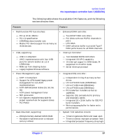 57
57 58
58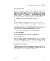 59
59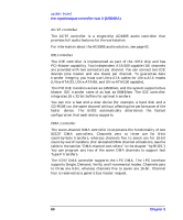 60
60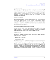 61
61