HP rp3440 Internal Cabling Guide for HP Smart Array Controllers - Page 31
Setting Up RAID on Hot Plug Drives A and B, Recabling for RAID - 4 dvd
 |
View all HP rp3440 manuals
Add to My Manuals
Save this manual to your list of manuals |
Page 31 highlights
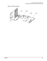
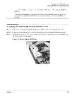
Cabling for the HP Integrity rx5670 Server Recabling for RAID NOTE To connect drives A, B, C, and D, follow all steps in both of the sections described below. Setting Up RAID on Hot Plug Drives A and B Step 1. Confirm the HP Smart Array 5302 or 5304 controller card is installed in PCI slot 4. See "Installing the HP Smart Array 5302 or 5304 Controller Card" on page 23. Step 2. Plug one end of the A9828-63001 cable into the controller card's internal PORT 1 connector. Rout the cable between the card and the side cover (see Figure 3-8). Step 3. Unplug the SCSI cable that connects the A and B hot plug drives to the MP/SCSI board located in PCI slot 1. There are two connectors on the MP/SCSI board. When looking at the MP/SCSI board, as shown in Figure 3-8, the connector towards the rear of the server goes to hot plug drives A and B. The connector towards the front of the server, where the drives are located, is for the DVD drive. Step 4. Take the unplugged SCSI cable and connect it to the A9828-63001 cable (see Figure 3-8). Once the cable is plugged in at both ends, it should be parallel to the side cover. Step 5. If only hot plug drives are required, the setup is complete and you may close the server. Otherwise continue on to the next section. Setting Up RAID on Hot Plug Drives C and D Step 1. Plug one end of the A9828-63002 cable into the controller card's internal PORT 2 connector. Step 2. Unplug the SCSI cable that connects the C and D hot plug drives to the MP/SCSI board located in PCI Slot 3. Step 3. Take the unplugged SCSI cable and connect it to the A9828-63002 cable (see Figure 3-8). Once the cable is plugged in at both ends, it should be parallel to the side cover. Step 4. When finished, close the server. Figure 3-8 Recabling for RAID NOTE Once the setup is complete, the cables should be parallel to the side cover. Chapter 3 27
-
 1
1 -
2
-
3
-
4
-
5
-
6
-
7
-
8
-
9
-
10
-
11
-
12
-
13
-
14
-
15
-
16
-
17
-
18
-
19
-
20
-
21
-
22
-
23
-
24
-
25
-
 26
26 -
 27
27 -
 28
28 -
 29
29 -
 30
30 -
 31
31 -
 32
32 -
 33
33 -
 34
34 -
 35
35 -
 36
36 -
37
-
38
-
39
-
40
-
41
-
42
-
43
-
44
-
45
-
46
-
47
-
48
-
49
-
50
-
51
-
52
-
53
-
54
-
55
-
56
-
57
-
58
-
59
-
60
 |
 |
