Hitachi HTS541010G9AT00 Specifications - Page 152
atile condition. When B = 1, MAX LBA/CYL-which is set by the Set Max ADDRESS
 |
UPC - 000061425019
View all Hitachi HTS541010G9AT00 manuals
Add to My Manuals
Save this manual to your list of manuals |
Page 152 highlights
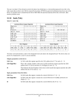
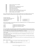
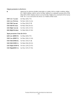
If a host protected area has been established by a Set Max Address Ext command, the device shall return command aborted Output parameters to the device Feature Destination code for this command 01h SET MAX SET PASSWORD 02h SET MAX LOCK 03h SET MAX UNLOCK 04h SET MAX FREEZE LOCK When the Set Max ADDRESS command is executed, this register is ignored. B This indicates the option bit for selection whether nonvolatile or volatile. B = 0 is the vol- atile condition. When B = 1, MAX LBA/CYL-which is set by the Set Max ADDRESS command-is preserved by POR and HARD RESET. When B = 0, MAX LBA/CYL- which is set by Set Max ADDRESS command-will be lost by POR and HARD RESET. B = 1 is not valid when the device is in Address Offset mode and the command is aborted. LBA Low In LBA mode, this register contains LBA bits 0 - 7 which is to be input (L=1). In CHS mode, this register is ignored. (L=0) LBA High/Mid In LBA mode, this register contains LBA bits 8 - 15 (Mid), 16 - 23 (High) which is to be set. (L=1) In CHS mode, this register contains max cylinder number which is to be set. (L=0) H In LBA mode this register contains LBA bits 24-27 which are to be input. (L = 1) In CHS mode this register is ignored. (L = 0) L This indicates the LBA addressing mode. L = 0 specifies the CHS mode and L=1 specifies the LBA addressing mode. D This indicates the device number bit. The device number bit of the Device/Head should be specified. D = 0 selects the master device and D = 1 selects the slave device. Input parameters from the device LBA Low In LBA mode this register contains the Adjusted max. LBA bits 0-7.(L = 1) In CHS mode this register contains the maximum LBA Low (= 63). (L = 0) LBA High/Mid In LBA mode this register contains the Adjusted max. LBA bits 8-15 (Mid) and bits 16-23 (High). (L = 1) In CHS mode this register contains the max cylinder number which is set. (L=0) H In LBA mode this register contains the Adjusted max. LBA bits 24-27. (L = 1) In CHS mode this register contains the maximum head number (= 15). (L = 0) Travelstar 5K100 (Serial ATA) Hard Disk Drive Specification 140
-
 1
1 -
2
-
3
-
4
-
5
-
6
-
7
-
8
-
9
-
10
-
11
-
12
-
13
-
14
-
15
-
16
-
17
-
18
-
19
-
20
-
21
-
22
-
23
-
24
-
25
-
26
-
27
-
28
-
29
-
30
-
31
-
32
-
33
-
34
-
35
-
36
-
37
-
38
-
39
-
40
-
41
-
42
-
43
-
44
-
45
-
46
-
47
-
48
-
49
-
50
-
51
-
52
-
53
-
54
-
55
-
56
-
57
-
58
-
59
-
60
-
61
-
62
-
63
-
64
-
65
-
66
-
67
-
68
-
69
-
70
-
71
-
72
-
73
-
74
-
75
-
76
-
77
-
78
-
79
-
80
-
81
-
82
-
83
-
84
-
85
-
86
-
87
-
88
-
89
-
90
-
91
-
92
-
93
-
94
-
95
-
96
-
97
-
98
-
99
-
100
-
101
-
102
-
103
-
104
-
105
-
106
-
107
-
108
-
109
-
110
-
111
-
112
-
113
-
114
-
115
-
116
-
117
-
118
-
119
-
120
-
121
-
122
-
123
-
124
-
125
-
126
-
127
-
128
-
129
-
130
-
131
-
132
-
133
-
134
-
135
-
136
-
137
-
138
-
139
-
140
-
141
-
142
-
143
-
144
-
145
-
146
-
 147
147 -
 148
148 -
 149
149 -
 150
150 -
 151
151 -
 152
152 -
 153
153 -
 154
154 -
 155
155 -
 156
156 -
 157
157 -
158
-
159
-
160
-
161
-
162
-
163
-
164
-
165
-
166
-
167
-
168
-
169
-
170
-
171
-
172
-
173
-
174
-
175
-
176
-
177
-
178
-
179
-
180
-
181
-
182
-
183
-
184
-
185
-
186
-
187
-
188
-
189
-
190
-
191
-
192
-
193
-
194
-
195
-
196
-
197
-
198
-
199
-
200
-
201
-
202
-
203
-
204
-
205
 |
 |
