Hitachi HTS541010G9AT00 Specifications - Page 51
Electrical interface specification - cable
 |
UPC - 000061425019
View all Hitachi HTS541010G9AT00 manuals
Add to My Manuals
Save this manual to your list of manuals |
Page 51 highlights
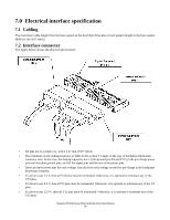
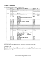
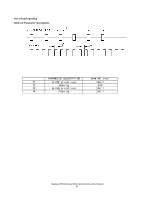
7.0 Electrical interface specification 7.1 Cabling The maximum cable length from the host system to the hard disk drive plus circuit pattern length in the host system shall not exceed 1 meter. 7.2 Interface connector The figure below shows the physical pin location. • All pins are in a single row, with a 1.27 mm (.050") pitch. • The comments on the mating sequence in Table in the section 7.3 apply to the case of backplane blind-mate connector only. In this case, the mating sequences are: (1) the ground pins P4 and P12; (2) the pre-charge power pins and the other ground pins; and (3) the signal pins and the rest of the power pins. • There are three power pins for each voltage. One pin from each voltage is used for pre-charge in the backplane blind-mate situation. • If a device uses 3.3 V, then all V33 pins must be terminated. Otherwise, it is optional to terminate any of the V33 pins. • If a device uses 5.0 V, then all V5 pins must be terminated. Otherwise, it is optional to terminate any of the V5 pins. • If a device uses 12.0 V, then all V12 pins must be terminated. Otherwise, it is optional to terminate any of the V12 pins. Travelstar 5K100 (Serial ATA) Hard Disk Drive Specification 39
-
 1
1 -
2
-
3
-
4
-
5
-
6
-
7
-
8
-
9
-
10
-
11
-
12
-
13
-
14
-
15
-
16
-
17
-
18
-
19
-
20
-
21
-
22
-
23
-
24
-
25
-
26
-
27
-
28
-
29
-
30
-
31
-
32
-
33
-
34
-
35
-
36
-
37
-
38
-
39
-
40
-
41
-
42
-
43
-
44
-
45
-
 46
46 -
 47
47 -
 48
48 -
 49
49 -
 50
50 -
 51
51 -
 52
52 -
 53
53 -
 54
54 -
 55
55 -
 56
56 -
57
-
58
-
59
-
60
-
61
-
62
-
63
-
64
-
65
-
66
-
67
-
68
-
69
-
70
-
71
-
72
-
73
-
74
-
75
-
76
-
77
-
78
-
79
-
80
-
81
-
82
-
83
-
84
-
85
-
86
-
87
-
88
-
89
-
90
-
91
-
92
-
93
-
94
-
95
-
96
-
97
-
98
-
99
-
100
-
101
-
102
-
103
-
104
-
105
-
106
-
107
-
108
-
109
-
110
-
111
-
112
-
113
-
114
-
115
-
116
-
117
-
118
-
119
-
120
-
121
-
122
-
123
-
124
-
125
-
126
-
127
-
128
-
129
-
130
-
131
-
132
-
133
-
134
-
135
-
136
-
137
-
138
-
139
-
140
-
141
-
142
-
143
-
144
-
145
-
146
-
147
-
148
-
149
-
150
-
151
-
152
-
153
-
154
-
155
-
156
-
157
-
158
-
159
-
160
-
161
-
162
-
163
-
164
-
165
-
166
-
167
-
168
-
169
-
170
-
171
-
172
-
173
-
174
-
175
-
176
-
177
-
178
-
179
-
180
-
181
-
182
-
183
-
184
-
185
-
186
-
187
-
188
-
189
-
190
-
191
-
192
-
193
-
194
-
195
-
196
-
197
-
198
-
199
-
200
-
201
-
202
-
203
-
204
-
205
 |
 |
