Hitachi HTS541010G9AT00 Specifications - Page 84
Data Out Commands
 |
UPC - 000061425019
View all Hitachi HTS541010G9AT00 manuals
Add to My Manuals
Save this manual to your list of manuals |
Page 84 highlights
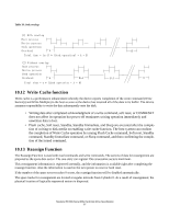
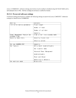
If an error occurs, the device will set BSY=0, ERR=1, and DRQ=1. The device will then store the error status in the Error Register. The registers will contain the location of the sector in error. The erroneous location will be reported with CHS mode or LBA mode, the mode is decided by mode select bit (bit 6) of Device register on issuing the command. If an Uncorrectable Data Error (UNC=1) occurs, the defective data will be transferred from the media to the sector buffer, and will be available to be transferred to the host, at the host's option. In case of Read Multiple command, the host should complete transfer the block which includes the error from the sector buffer and terminate whatever kind of type of error occurred. All data transfers to the host through the Data Register are 16 bits, except for the ECC bytes, which are 8 bits. 11.2 Data Out Commands The following are Data Out commands: • Device Configuration SET • Format Track • Security Disable Password • Security Erase Unit • Security Set Password • Security Unlock • Set Max Set Password • Set Max Unlock • S.M.A.R.T. Write log sector • Write Buffer • Write Log Ext • Write Long • Write Multiple • Write Multiple Ext • Write Sector(s) • Write Sector(s) Ext Execution includes the transfer of one or more 512 byte (> 512 bytes on Write Long) sectors of data from the host to the device. Execution includes the transfer of one or more 512 byte (>512 bytes on Write Long) sectors of data from the host to the device. If the device detects an invalid parameter, then it will abort the command by setting BSY=0, ERR=1, ABT=1. If an uncorrectable error occurs, the device will set BSY=0 and ERR=1, store the error status in the Error Register. The registers will contain the location of the sector in error. The errored location will be reported with CHS mode or LBA mode. The mode is decided by mode select bit (bit 6) of Device register on issuing the command. All data transfers to the device through the Data Register are 16 bits, except for the ECC bytes, which are 8 bits. Travelstar 5K100 (Serial ATA) Hard Disk Drive Specification 72
-
 1
1 -
2
-
3
-
4
-
5
-
6
-
7
-
8
-
9
-
10
-
11
-
12
-
13
-
14
-
15
-
16
-
17
-
18
-
19
-
20
-
21
-
22
-
23
-
24
-
25
-
26
-
27
-
28
-
29
-
30
-
31
-
32
-
33
-
34
-
35
-
36
-
37
-
38
-
39
-
40
-
41
-
42
-
43
-
44
-
45
-
46
-
47
-
48
-
49
-
50
-
51
-
52
-
53
-
54
-
55
-
56
-
57
-
58
-
59
-
60
-
61
-
62
-
63
-
64
-
65
-
66
-
67
-
68
-
69
-
70
-
71
-
72
-
73
-
74
-
75
-
76
-
77
-
78
-
 79
79 -
 80
80 -
 81
81 -
 82
82 -
 83
83 -
 84
84 -
 85
85 -
 86
86 -
 87
87 -
 88
88 -
 89
89 -
90
-
91
-
92
-
93
-
94
-
95
-
96
-
97
-
98
-
99
-
100
-
101
-
102
-
103
-
104
-
105
-
106
-
107
-
108
-
109
-
110
-
111
-
112
-
113
-
114
-
115
-
116
-
117
-
118
-
119
-
120
-
121
-
122
-
123
-
124
-
125
-
126
-
127
-
128
-
129
-
130
-
131
-
132
-
133
-
134
-
135
-
136
-
137
-
138
-
139
-
140
-
141
-
142
-
143
-
144
-
145
-
146
-
147
-
148
-
149
-
150
-
151
-
152
-
153
-
154
-
155
-
156
-
157
-
158
-
159
-
160
-
161
-
162
-
163
-
164
-
165
-
166
-
167
-
168
-
169
-
170
-
171
-
172
-
173
-
174
-
175
-
176
-
177
-
178
-
179
-
180
-
181
-
182
-
183
-
184
-
185
-
186
-
187
-
188
-
189
-
190
-
191
-
192
-
193
-
194
-
195
-
196
-
197
-
198
-
199
-
200
-
201
-
202
-
203
-
204
-
205
 |
 |
