Hitachi HTS541010G9AT00 Specifications - Page 90
cessing the command and has interrupted the host.
 |
UPC - 000061425019
View all Hitachi HTS541010G9AT00 manuals
Add to My Manuals
Save this manual to your list of manuals |
Page 90 highlights
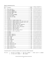
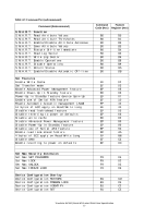
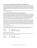
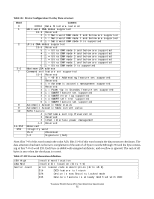
The "Command Set (Subcommand)" table above shows the sub-commands that are supported by each command or feature. The following symbols are used in the command descriptions: Input registers 0 This indicates that the bit is always set to 0. 1 This indicates that the bit is always set to 1. H Head number. This indicates that the head number part of the Device/Head Register is an input parameter and will be set by the device. V Valid. This indicates that the bit is part of an input parameter and will be set by the device to 0 or 1. N Not recommended condition for start up. Indicates that the condition of the device is not recommended for start up. - This indicates that the bit is not part of an input parameter. Out put registers 0 This indicates that the bit must be set to 0. 1 This indicates that the bit must be set to 1. D The device number bit. This indicates that the device number bit of the Device Register should be specified. Zero selects the master device and one selects the slave device. H Head number. This indicates that the head number part of the Device/Head Register is an output parameter and should be specified. L LBA mode. This indicates the addressing mode. Zero specifies CHS mode and one specifies LBA addressing mode. R Retry. Original meaning is already obsolete, there is no difference between 0 and 1. (Using 0 is recommended for future compatibility.) B Option Bit. This indicates that the Option Bit of the Sector Count Register be specified. (This bit is used by Set Max ADDRESS command.) V Valid. This indicates that the bit is part of an output parameter and should be specified. x This indicates that the hex character is not used. - This indicates that the bit is not used. The command descriptions show the contents of the Status and Error Registers after the device has completed processing the command and has interrupted the host. Travelstar 5K100 (Serial ATA) Hard Disk Drive Specification 78
-
 1
1 -
2
-
3
-
4
-
5
-
6
-
7
-
8
-
9
-
10
-
11
-
12
-
13
-
14
-
15
-
16
-
17
-
18
-
19
-
20
-
21
-
22
-
23
-
24
-
25
-
26
-
27
-
28
-
29
-
30
-
31
-
32
-
33
-
34
-
35
-
36
-
37
-
38
-
39
-
40
-
41
-
42
-
43
-
44
-
45
-
46
-
47
-
48
-
49
-
50
-
51
-
52
-
53
-
54
-
55
-
56
-
57
-
58
-
59
-
60
-
61
-
62
-
63
-
64
-
65
-
66
-
67
-
68
-
69
-
70
-
71
-
72
-
73
-
74
-
75
-
76
-
77
-
78
-
79
-
80
-
81
-
82
-
83
-
84
-
 85
85 -
 86
86 -
 87
87 -
 88
88 -
 89
89 -
 90
90 -
 91
91 -
 92
92 -
 93
93 -
 94
94 -
 95
95 -
96
-
97
-
98
-
99
-
100
-
101
-
102
-
103
-
104
-
105
-
106
-
107
-
108
-
109
-
110
-
111
-
112
-
113
-
114
-
115
-
116
-
117
-
118
-
119
-
120
-
121
-
122
-
123
-
124
-
125
-
126
-
127
-
128
-
129
-
130
-
131
-
132
-
133
-
134
-
135
-
136
-
137
-
138
-
139
-
140
-
141
-
142
-
143
-
144
-
145
-
146
-
147
-
148
-
149
-
150
-
151
-
152
-
153
-
154
-
155
-
156
-
157
-
158
-
159
-
160
-
161
-
162
-
163
-
164
-
165
-
166
-
167
-
168
-
169
-
170
-
171
-
172
-
173
-
174
-
175
-
176
-
177
-
178
-
179
-
180
-
181
-
182
-
183
-
184
-
185
-
186
-
187
-
188
-
189
-
190
-
191
-
192
-
193
-
194
-
195
-
196
-
197
-
198
-
199
-
200
-
201
-
202
-
203
-
204
-
205
 |
 |
