Hitachi HTS541010G9AT00 Specifications - Page 93
DEVICE CONFIGURATION IDENTIFY subcommand C2h, DEVICE CONFIGURATION SET subcommand C3h
 |
UPC - 000061425019
View all Hitachi HTS541010G9AT00 manuals
Add to My Manuals
Save this manual to your list of manuals |
Page 93 highlights
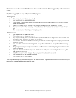
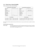
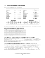
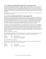
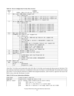
12.2.3 DEVICE CONFIGURATION IDENTIFY (subcommand C2h) The DEVICE CONFIGURATION IDENTIFY command returns a 512 byte data structure via PIO data-in transfer. The content of this data structure indicates the selectable commands, modes, and feature sets that the device is capable of supporting. If a DEVICE CONFIGURATION SET command has been issued reducing the capabilities, the response to an IDENTIFY DEVICE or IDENTIFY PACKET DEVICE command will reflect the reduced set of capabilities, while the DEVICE CONFIGURATION IDENTIFY command will reflect the entire set of selectable capabilities. The format of the Device Configuration Overlay data structure is shown in Table 46: "Device Configuration Overlay Data structure" on page 82. 12.2.4 DEVICE CONFIGURATION SET (subcommand C3h) The DEVICE CONFIGURATION SET command allows a device manufacturer or a personal computer system manufacturer to reduce the set of optional commands, modes, or feature sets supported by a device as indicated by a DEVICE CONFIGURATION IDENTIFY command. The DEVICE CONFIGURATION SET command transfers an overlay that modifies some of the bits set in words 63, 78, 79 82, 83, 84, and 88 of the IDENTIFY DEVICE command response. When the bits in these words are cleared, the device no longer supports the indicated command, mode, or feature set. If a bit is set in the overlay transmitted by the device that is not set in the overlay received from a DEVICE CONFIGURATION IDENTIFY command, no action is taken for that bit. The format of the overlay transmitted by the device is described in the table in Table 46: "Device Configuration Overlay Data structure" on page 82. The restrictions on changing these bits is described in the text following that table. If any of the bit modification restrictions described are violated or any setting is changed with DEVICE CONFIGURATION SET command, the device shall return command aborted. In that case, error reason code is returned to sector count register, invalid word location is returned to LBA high register, and invalid bit location is returned to LBA Mid register. The Definition of error information is shown in Table 47: "DCO error information definition." on page 82. ERROR INFORMATION EXAMPLE 1: After establishing a protected area with SET MAX address, if a user attempts to change maximum LBA address (DC SET or DC RESTORE), the device aborts that command and returns error reason code as below. LBA High LBA Mid Sector count : 03h : 00h : 06h = word 3 is invalid this register is not assigned in this case = Protected area is now established ERROR INFORMATION EXAMPLE 2: When the device is enabled and the Security feature is set, if the user attempts to disable that feature, the device aborts that command and returns an error reason code as below. LBA High LBA Mid Sector count : 07h : 03h : 04h = word 7 is invalid = bit 3 is invalid = now Security feature set is enabled Travelstar 5K100 (Serial ATA) Hard Disk Drive Specification 81
-
 1
1 -
2
-
3
-
4
-
5
-
6
-
7
-
8
-
9
-
10
-
11
-
12
-
13
-
14
-
15
-
16
-
17
-
18
-
19
-
20
-
21
-
22
-
23
-
24
-
25
-
26
-
27
-
28
-
29
-
30
-
31
-
32
-
33
-
34
-
35
-
36
-
37
-
38
-
39
-
40
-
41
-
42
-
43
-
44
-
45
-
46
-
47
-
48
-
49
-
50
-
51
-
52
-
53
-
54
-
55
-
56
-
57
-
58
-
59
-
60
-
61
-
62
-
63
-
64
-
65
-
66
-
67
-
68
-
69
-
70
-
71
-
72
-
73
-
74
-
75
-
76
-
77
-
78
-
79
-
80
-
81
-
82
-
83
-
84
-
85
-
86
-
87
-
 88
88 -
 89
89 -
 90
90 -
 91
91 -
 92
92 -
 93
93 -
 94
94 -
 95
95 -
 96
96 -
 97
97 -
 98
98 -
99
-
100
-
101
-
102
-
103
-
104
-
105
-
106
-
107
-
108
-
109
-
110
-
111
-
112
-
113
-
114
-
115
-
116
-
117
-
118
-
119
-
120
-
121
-
122
-
123
-
124
-
125
-
126
-
127
-
128
-
129
-
130
-
131
-
132
-
133
-
134
-
135
-
136
-
137
-
138
-
139
-
140
-
141
-
142
-
143
-
144
-
145
-
146
-
147
-
148
-
149
-
150
-
151
-
152
-
153
-
154
-
155
-
156
-
157
-
158
-
159
-
160
-
161
-
162
-
163
-
164
-
165
-
166
-
167
-
168
-
169
-
170
-
171
-
172
-
173
-
174
-
175
-
176
-
177
-
178
-
179
-
180
-
181
-
182
-
183
-
184
-
185
-
186
-
187
-
188
-
189
-
190
-
191
-
192
-
193
-
194
-
195
-
196
-
197
-
198
-
199
-
200
-
201
-
202
-
203
-
204
-
205
 |
 |