Hitachi NT65MA3 Instruction Manual - Page 15
Fig. 7, Control valve During return: Fig. 7 and Fig. 8
 |
UPC - 717709011281
View all Hitachi NT65MA3 manuals
Add to My Manuals
Save this manual to your list of manuals |
Page 15 highlights
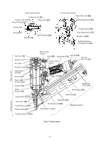
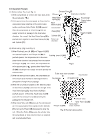
(3) During return: (Fig. 7 and Fig. 8) Exhaust Cover [5] 1) When either Pushing Lever (A) [40] or Trigger (A) Exhaust vent Head valve chamber [53] is released, Plunger (A) [68] goes down and the Head compressed air in the accumulator flows into the Valve (A) [10] valve piston lower chamber. 2) As the air pressure in the valve piston lower chamber Accumulator Air passage Control valve section increases to overcome the air pressure applied on the upper portion of Valve Piston (B) [65], Valve Piston (B) [65] is forced upward. When this occurs, Cylinder [11] Return air chamber the exhaust valve is closed and the air supply vent is Trigger (A) [53] opened. Piston [15] 3) When the air supply vent opens, the compressed air in the accumulator ( ) passes through the air Piston Bumper [25] passage and flows into the head valve chamber to Driver blade push down Head Valve (A) [10]. As a result, Head Valve (A) [10] and the Cylinder [11] are sealed and, Pushing Lever (A) [40] at the same time, Head Valve (A) [10] and the Exhaust Cover [5] are released to open the exhaust vent. 4) The compressed air at the upper portion of the Piston [15] is discharged into the atmosphere Fig. 7 To the head valve chamber Accumulator Air passage Air supply vent through the exhaust vent. In this way, the air pressure at the upper portion of the Piston [15] is reduced, and the greater pressure of the air accumulated in the return air chamber pushes the Piston [15] upward. 5) If the air pressure at the lower portion of the Piston [15] is higher than that of the atmosphere after the Piston [15] has fully returned, the excess air pressure is discharged into the atmosphere through Plunger (A) [68] Exhaust valve Valve Piston (B) [65] Valve piston lower chamber the clearance between the Piston Bumper [25] and Fig. 8 Control valve section the driver blade. --- 12 ---
-
 1
1 -
2
-
3
-
4
-
5
-
6
-
7
-
8
-
9
-
 10
10 -
 11
11 -
 12
12 -
 13
13 -
 14
14 -
 15
15 -
 16
16 -
 17
17 -
 18
18 -
 19
19 -
 20
20 -
21
-
22
-
23
-
24
-
25
-
26
-
27
-
28
-
29
-
30
-
31
-
32
-
33
-
34
-
35
-
36
-
37
 |
 |
