Hitachi NT65MA3 Instruction Manual - Page 28
Disassembly and Reassembly of the Driving Socket Hd. Bolts M6 x 30
 |
UPC - 717709011281
View all Hitachi NT65MA3 manuals
Add to My Manuals
Save this manual to your list of manuals |
Page 28 highlights
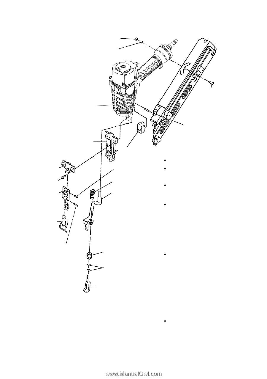
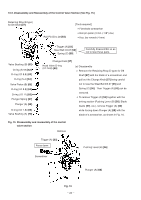
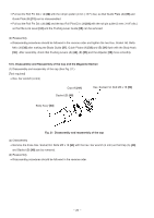
10-4. Disassembly and Reassembly of the Driving Section (See Fig. 20.) Nylon Nut M5 [44] Sleeve [45] Body Ass'y [30] Hex. Socket Hd. Bolt (W/Flange) M5 x 20 [78] Roll Pin D3 x 28 [54] Blade Guide [37] Guide Plate (B) [31] Hex. Socket Hd. Bolt M6 x 30 [32] Guide Plate (A) [33] Pushing Lever Guide [58] [Tools required] Hex. bar wrenches (4 mm and 5 mm) Roll Pin D4 x 14 [42] Holder Spring [35] Roll pin pullers (3 mm (.118") dia. and 4 mm (.157") dia.) Flat-blade head screwdriver with small tip Pushing Lever (B) [36] (a) Disassembly Continuously turn the Adjuster [38] in the direction in which the nail is raised when Lock Lever [34] adjusting the driving depth (refer to ADJUSTING THE NAILING DEPTH on page 21 in the Instruction Manual) so that Roll Pin D3 x 20 [43] Adjuster [38] Pushing Lever (A) [40] can be removed. Remove the Hex. Socket Hd. Bolt (W/ Ratchet Spring [39] Flange) M5 x 20 [78] with the hex. bar wrench (4 mm) and remove the two Hex. Pushing Lever (A) [40] Socket Hd. Bolts M6 x 30 [32] with the hex. bar wrench (5 mm). Now, the Blade Guide [37], Guide Plates (A) [33] and (B) Fig. 20 Disassembly and reassembly of the driving section [31], Pushing Lever (B) [36], etc. can be removed. Remove the two Ratchet Springs [39] from the Adjuster [38] with the small flat- blade screwdriver being very careful not to lose them. Now, the Adjuster [38] can be removed from Pushing Lever (B) [36]. --- 25 ---
-
 1
1 -
2
-
3
-
4
-
5
-
6
-
7
-
8
-
9
-
10
-
11
-
12
-
13
-
14
-
15
-
16
-
17
-
18
-
19
-
20
-
21
-
22
-
 23
23 -
 24
24 -
 25
25 -
 26
26 -
 27
27 -
 28
28 -
 29
29 -
 30
30 -
 31
31 -
 32
32 -
 33
33 -
34
-
35
-
36
-
37
 |
 |