Hitachi NT65MA3 Instruction Manual - Page 29
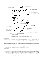
Disassembly and Reassembly of the Cap and the Magazine Pull out the Roll Pin D3 x 20
 |
UPC - 717709011281
View all Hitachi NT65MA3 manuals
Add to My Manuals
Save this manual to your list of manuals |
Page 29 highlights
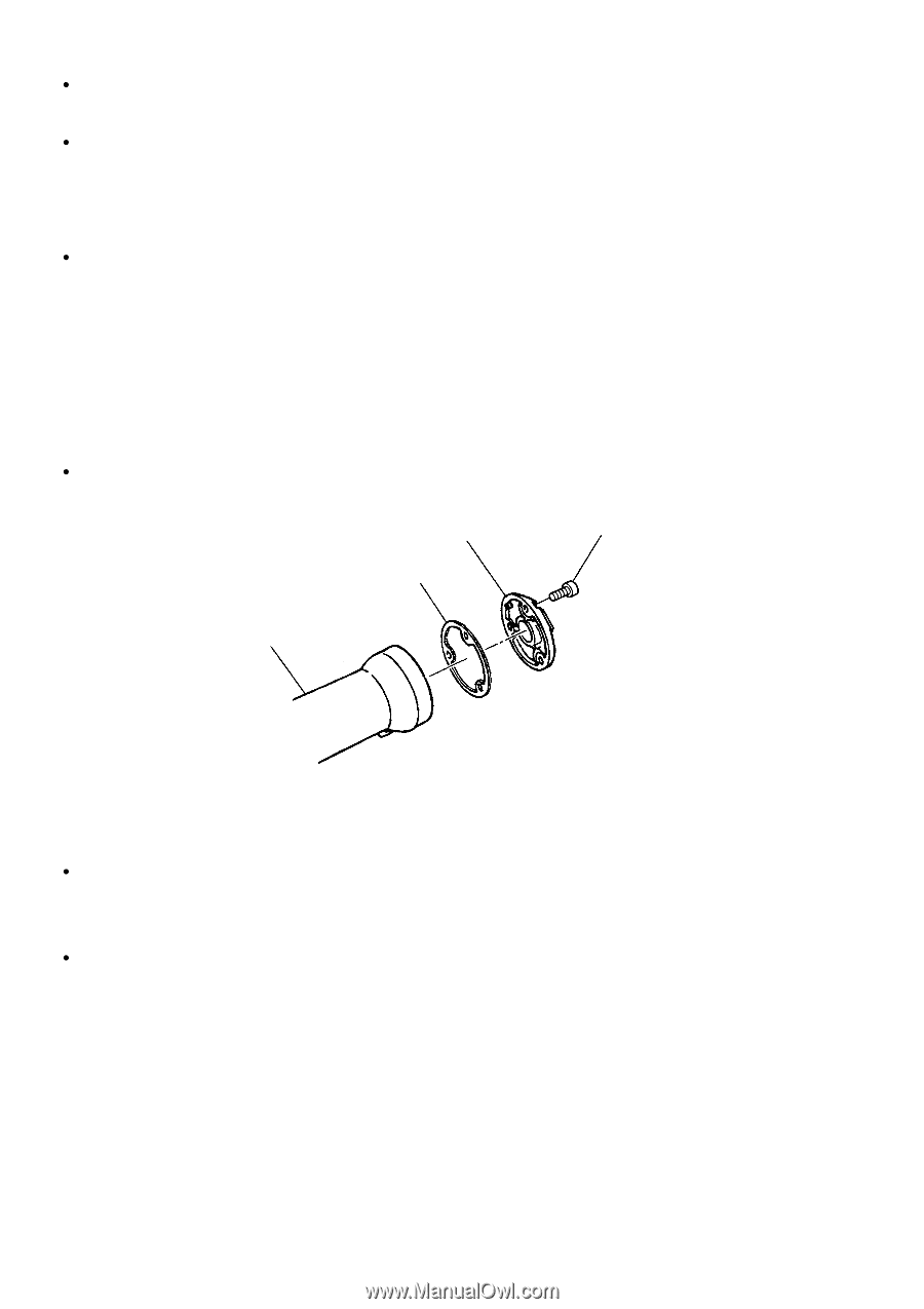
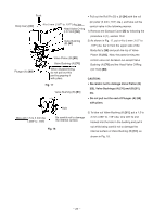
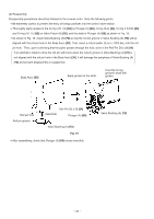
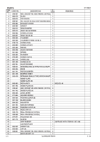
Pull out the Roll Pin D4 x 14 [42] with the roll pin puller (4 mm (.157") dia.) so that Guide Plate (A) [33] and Guide Plate (B) [31] can be disassembled. Pull out the Roll Pin D3 x 20 [43] and the two Roll Pins D3 x 28 [54] with the roll pin puller (3 mm (.118") dia.) so that the Lock Lever [34] and the Pushing Lever Guide [58] can be removed. (b) Reassembly Disassembly procedures should be followed in the reverse order and tighten the two Hex. Socket Hd. Bolts M6 x 30 [32] after making the Blade Guide [37], Guide Plates (A) [33] and (B) [31] flush with the Body Ass'y [30]. After assembly, check that Pushing Levers (A) [40], (B) [36] and the Adjuster [38] move smoothly. 10-5. Disassembly and Reassembly of the Cap and the Magazine Section (1) Disassembly and reassembly of the cap (See Fig. 21.) [Tool required] Hex. bar wrench (4 mm) Cap (A) [49] Gasket (B) [48] Hex. Socket Hd. Bolt M5 x 16 [50] Body Ass'y [30] Fig. 21 Disassembly and reassembly of the cap (a) Disassembly Remove the three Hex. Socket Hd. Bolts M5 x 16 [50] with the hex. bar wrench (4 mm) so that Cap (A) [49] and Gasket (B) [48] can be removed. (b) Reassembly Disassembly procedures should be followed in the reverse order. --- 26 ---
-
 1
1 -
2
-
3
-
4
-
5
-
6
-
7
-
8
-
9
-
10
-
11
-
12
-
13
-
14
-
15
-
16
-
17
-
18
-
19
-
20
-
21
-
22
-
23
-
 24
24 -
 25
25 -
 26
26 -
 27
27 -
 28
28 -
 29
29 -
 30
30 -
 31
31 -
 32
32 -
 33
33 -
 34
34 -
35
-
36
-
37
 |
 |