Hitachi NT65MA3 Instruction Manual - Page 27
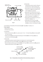
As shown in Fig. 19, install Valve Bushing A, and O-ring I.D 11
 |
UPC - 717709011281
View all Hitachi NT65MA3 manuals
Add to My Manuals
Save this manual to your list of manuals |
Page 27 highlights
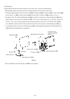
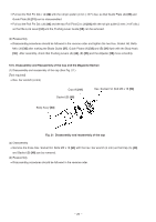
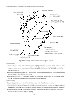
(b) Reassembly Disassembly procedures should be followed in the reverse order. Note the following points: Be extremely careful to prevent the entry of foreign particles into the control valve section. Thoroughly apply grease to the O-ring (I.D 1.8) [69] on Plunger (A) [68], O-ring (S-4) [64], O-ring (I.D 8.8) [63] and O-ring (I.D 11) [66] on Valve Piston (B) [65], and the shaft of Plunger (A) [68] as shown in Fig. 19. As shown in Fig. 19, install Valve Bushing (A) [70] so that the roll pin groove in Valve Bushing (A) [70] will be aligned with the roll pin hole in the Body Ass'y [30]. First, insert a roll pin puller (3 mm (.118") dia.) into the roll pin hole. Then, upon confirming that the puller passes through the hole, drive in the Roll Pin D3 x 28 [54]. If an attempt is made to drive the roll pin with force when the roll pin groove in Valve Bushing (A) [70] is not aligned with the roll pin hole in the Body Ass'y [30], it will damage the periphery of Valve Bushing (A) [70] and prevent disassembly or reassembly. Body Ass'y [30] Apply grease to the stem. Coat the O-ring groove's shaft with grease. Roll pin hole Roll pin groove Roll Pin D3 x 28 [54] Assemble Plunger (A) [68] Valve Bushing (A) [70] Fig. 19 After assembling, check that Plunger (A) [68] moves smoothly. Valve Bushing (A) [70] --- 24 ---
-
 1
1 -
2
-
3
-
4
-
5
-
6
-
7
-
8
-
9
-
10
-
11
-
12
-
13
-
14
-
15
-
16
-
17
-
18
-
19
-
20
-
21
-
 22
22 -
 23
23 -
 24
24 -
 25
25 -
 26
26 -
 27
27 -
 28
28 -
 29
29 -
 30
30 -
 31
31 -
 32
32 -
33
-
34
-
35
-
36
-
37
 |
 |
