Hitachi NT65MA3 Instruction Manual - Page 26
], Valve Bushings A [70] and B [61], Pull out the Roll Pin D3 x 28
 |
UPC - 717709011281
View all Hitachi NT65MA3 manuals
Add to My Manuals
Save this manual to your list of manuals |
Page 26 highlights
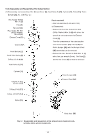
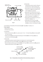
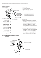
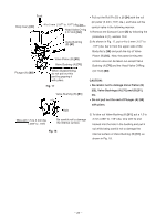
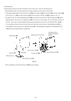
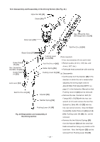
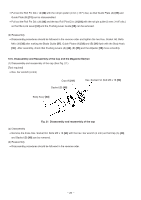
Push Pull out the Roll Pin D3 x 28 [54] with the roll Body Ass'y [30] 4 to 5 mm (.157" to .197") dia. bar Head Valve O-ring (I.D 16.8) [60] pin puller (3 mm (.118") dia.), and take out the control valve in the following manner. 1) Remove the Exhaust Cover [5] by following the procedure in (1), section 10-2. Valve Bushing (B) [61] 2) As shown in Fig. 17, put a 4 to 5 mm (.157" to .197") dia. bar in from the upper side of the Body Ass'y [30] and push the top of Valve Valve Piston (B) [65] Valve Bushing (A) [70] Piston (B) [65]. Now, the parts forming the control valve can be taken out except Valve Bushing (A) [70] and the Head Valve O-Ring Plunger (A) [68] When disassembling, do not pull out this part by gripping it with pliers. (I.D 16.8) [60]. CAUTION: Fig. 17 Valve Bushing (B) [61] Be careful not to damage Valve Piston (B) [65], Valve Bushings (A) [70] and (B) [61], etc. Do not pull out the end of Plunger (A) [68] with pliers. Hole 3) To take out Valve Bushing (B) [61], put a 1.5 to Wire with 1.5 to 3 mm dia. (.059" to .118") Be careful not to damage the internal surface. 3 mm (.059" to .118") dia. wire with its end hooked into the hole in the bushing and pull it Fig. 18 out while being careful not to damage the internal surface of Valve Bushing (B) [61], as shown in Fig. 18. --- 23 ---
-
 1
1 -
2
-
3
-
4
-
5
-
6
-
7
-
8
-
9
-
10
-
11
-
12
-
13
-
14
-
15
-
16
-
17
-
18
-
19
-
20
-
 21
21 -
 22
22 -
 23
23 -
 24
24 -
 25
25 -
 26
26 -
 27
27 -
 28
28 -
 29
29 -
 30
30 -
 31
31 -
32
-
33
-
34
-
35
-
36
-
37
 |
 |
