Hitachi NT65MA3 Instruction Manual - Page 22
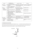
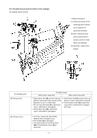
DISASSEMBLY AND REASSEMBLY, 10-1. General Precautions in Disassembly and Reassembly - diagram
 |
UPC - 717709011281
View all Hitachi NT65MA3 manuals
Add to My Manuals
Save this manual to your list of manuals |
Page 22 highlights
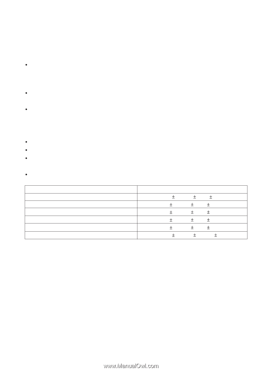
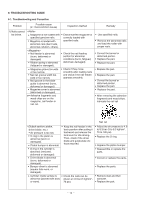
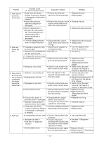
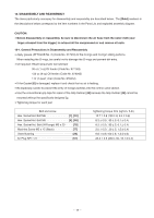
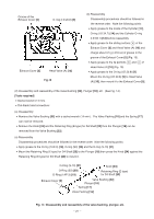
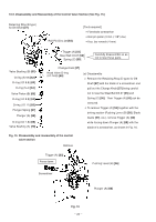
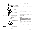
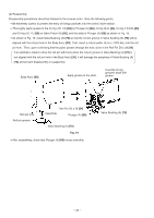
10. DISASSEMBLY AND REASSEMBLY The items particularly necessary for disassembly and reassembly are described below. The [Bold] numbers in the descriptions below correspond to the item numbers in the Parts List and exploded assembly diagram. CAUTION: Before disassembly or reassembly, be sure to disconnect the air hose from the nailer (with your finger released from the trigger) to exhaust all the compressed air and remove all nails. 10-1. General Precautions in Disassembly and Reassembly Apply grease (ATTOLUB No. 2) (Code No. 317918) to the O-rings and O-rings' sliding portions. When installing the O-rings, be careful not to damage the O-rings and prevent dirt entry. Oil required: Hitachi pneumatic tool lubricant 30 cc (1 oz) Oil feeder (Code No. 877153) 120 cc (4 oz) Oil feeder (Code No. 874042) 1 ltr (1 quart ) Can (Code No. 876212) If the Gasket [6] is damaged, replace it and check that no air is leaking. Be especially careful to prevent the entry of foreign particles into the control valve section. Use the conventional grip tape for repair of the Grip Rubber [46] because the Grip Rubber [46] cannot be mounted without the specifically designed jig. Tightening torque for each part Bolt and screw Hex. Socket Hd. Bolt M6 1], [32] Hex. Socket Hd. Bolt M5 4], [50] Hex. Socket Hd. Bolt (W/Flange) M5 x 20 78] Machine Screw M5 x 15 (Black 77] Valve Bushing [22 Air Plug NPT 1/4 [51 Tightening torque N•m (kgf•cm, ft-lb) 12.7 0.8 (130 8, 9.4 0.6) 8.3 0.5 ( 85 5, 6.1 0.4) 8.3 0.5 ( 85 5, 6.1 0.4) 2.0 0.5 ( 20 5, 1.5 0.4) 9.8 0.8 (100 8, 7.2 0.6) 24.5 0.5 (250 50, 18.1 0.4) --- 19 ---
-
 1
1 -
2
-
3
-
4
-
5
-
6
-
7
-
8
-
9
-
10
-
11
-
12
-
13
-
14
-
15
-
16
-
 17
17 -
 18
18 -
 19
19 -
 20
20 -
 21
21 -
 22
22 -
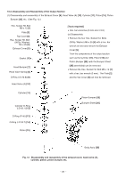 23
23 -
 24
24 -
 25
25 -
 26
26 -
 27
27 -
28
-
29
-
30
-
31
-
32
-
33
-
34
-
35
-
36
-
37
 |
 |