Honeywell HJC5000 User Guide - Page 33
AC Power Adapter with CEE 7/16 Europlug, Table 3-1
 |
View all Honeywell HJC5000 manuals
Add to My Manuals
Save this manual to your list of manuals |
Page 33 highlights
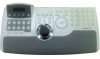
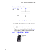
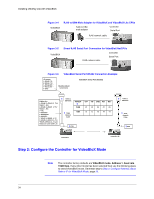
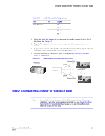
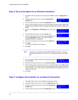
UltraKey Lite Controller Installation and User Guide Table 3-1 Serial Port COM1 Serial Port COM1 and COM2 Pin Assignments Type Pin RS422 1 2 5 7 8 RS485 7 8 Signal RX + RX - GND TX - TX + T/R - T/R + Note For a list of accessories see Shipping Checklist on page 18 and for port connections see UltraKey Lite Port Connections and Descriptions on page 19. 1. Select the applicable adapter plug and insert it into the AC adapter. Push to click it into place. See Figure 3-3. 2. Plug the AC adapter into the controller power port and the adapter into a power source. 3. Connect an RJ45 network cable to the controller serial port. 4. Connect the RJ45 network cable to VideoBloX: • For backwards compatibility with VideoBloX and VideoBloX Lite CPUs, an RJ45 to DB9 male adapter is required and included with your shipment. See Figure 3-4. • For VideoBloX NetCPU, the installation is a direct connection with the RJ45 network cable, also included. See Figure 3-5 and Figure 3-6. Figure 3-3 AC Power Adapter with CEE 7/16 Europlug Slide plug onto the adapter and snap into place Document 800-07422 Rev A 33 08/10
-
 1
1 -
2
-
3
-
4
-
5
-
6
-
7
-
8
-
9
-
10
-
11
-
12
-
13
-
14
-
15
-
16
-
17
-
18
-
19
-
20
-
21
-
22
-
23
-
24
-
25
-
26
-
27
-
 28
28 -
 29
29 -
 30
30 -
 31
31 -
 32
32 -
 33
33 -
 34
34 -
 35
35 -
 36
36 -
 37
37 -
 38
38 -
39
-
40
-
41
-
42
-
43
-
44
-
45
-
46
-
47
-
48
-
49
-
50
-
51
-
52
-
53
-
54
-
55
-
56
-
57
-
58
-
59
-
60
-
61
-
62
-
63
-
64
-
65
-
66
-
67
-
68
-
69
-
70
-
71
-
72
 |
 |
