Honeywell HJC5000 User Guide - Page 37
Ethernet Port Connections to VideoBloX, Table 3-2, RJ45 Ethernet Pin Assignments, Signal
 |
View all Honeywell HJC5000 manuals
Add to My Manuals
Save this manual to your list of manuals |
Page 37 highlights
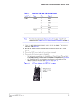
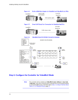
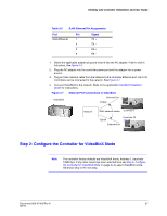
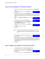
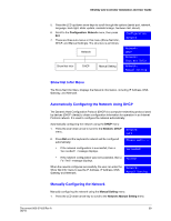
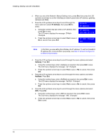
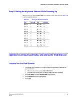
UltraKey Lite Controller Installation and User Guide Table 3-2 RJ45 Ethernet Pin Assignments Port Pin RJ45 Ethernet 1 2 3 6 Signal TX + TX - RX+ RX - 1. Select the applicable adapter plug and insert it into the AC adapter. Push to click it into place. See Figure 3-3. 2. Plug the AC adapter into the controller power port and the adapter into a power source. 3. Plug an RJ45 network cable from the network to the controller Ethernet port. Up to 32 controllers can be connected to the network. See Figure 3-7. 4. Connect VideoBloX to the network. Refer to the applicable VideoBloX Installation Guide for instructions. Figure 3-7 VideoBloX Ethernet Port Connections to VideoBloX Ethernet Port TCP/IP Network RJ45 network cables Controller 1 TCP/IP Controller 32 Ethernet Port Step 2: Configure the Controller for VideoBloX Mode Note The controller factory defaults are VideoBloX mode, Address 1, baud rate 19200 bps. If any other mode has been selected then see Step 2: Configure the Controller for VideoBloX Mode on page 34 to select VideoBloX mode. Otherwise skip to the next step. Document 800-07422 Rev A 37 08/10
-
 1
1 -
2
-
3
-
4
-
5
-
6
-
7
-
8
-
9
-
10
-
11
-
12
-
13
-
14
-
15
-
16
-
17
-
18
-
19
-
20
-
21
-
22
-
23
-
24
-
25
-
26
-
27
-
28
-
29
-
30
-
31
-
 32
32 -
 33
33 -
 34
34 -
 35
35 -
 36
36 -
 37
37 -
 38
38 -
 39
39 -
 40
40 -
 41
41 -
 42
42 -
43
-
44
-
45
-
46
-
47
-
48
-
49
-
50
-
51
-
52
-
53
-
54
-
55
-
56
-
57
-
58
-
59
-
60
-
61
-
62
-
63
-
64
-
65
-
66
-
67
-
68
-
69
-
70
-
71
-
72
 |
 |
