Honeywell HJC5000 User Guide - Page 43
Step 3A: Con the Controller for a Serial Port Connection
 |
View all Honeywell HJC5000 manuals
Add to My Manuals
Save this manual to your list of manuals |
Page 43 highlights
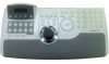
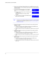
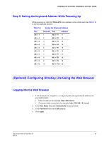
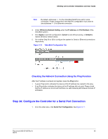
UltraKey Lite Controller Installation and User Guide Note By default, addresses 1- 5 in the VideoBloX NetCPU are set for serial connection. Please change this in the NetCPU configuration if you want to use addresses 1- 5 for Ethernet connection. 3. Under VB Device Network Setting, enter the IP address and Port Number of the VideoBloX system. 4. Click Apply to save the configuration, Cancel to exit without saving, or Default to restore all factory default values. 5. Go to either Step 3A or 3B to configure the system for Serial or Ethernet connections respectively. Figure 3-10 VideoBloX Configuration Tab Checking the Network Connection Using the Ping Function After the IP address is entered and applied, press the Ping button. • A green Ping button indicates the device at this IP address has replied to the ping. • A red Ping button indicates the device at the IP address did not reply. Please check that the IP address is correct and that there is a valid network path between the two IP addresses. Step 3A: Configure the Controller for a Serial Port Connection 1. From the side menu, click Serial Port Configuration. See Figure 3-11. Document 800-07422 Rev A 43 08/10
-
 1
1 -
2
-
3
-
4
-
5
-
6
-
7
-
8
-
9
-
10
-
11
-
12
-
13
-
14
-
15
-
16
-
17
-
18
-
19
-
20
-
21
-
22
-
23
-
24
-
25
-
26
-
27
-
28
-
29
-
30
-
31
-
32
-
33
-
34
-
35
-
36
-
37
-
 38
38 -
 39
39 -
 40
40 -
 41
41 -
 42
42 -
 43
43 -
 44
44 -
 45
45 -
 46
46 -
 47
47 -
 48
48 -
49
-
50
-
51
-
52
-
53
-
54
-
55
-
56
-
57
-
58
-
59
-
60
-
61
-
62
-
63
-
64
-
65
-
66
-
67
-
68
-
69
-
70
-
71
-
72
 |
 |