Husqvarna AUTOMOWER 535 AWD Owner Manual - Page 17
To examine where to put the power supply, max. 5 cm / 2
 |
View all Husqvarna AUTOMOWER 535 AWD manuals
Add to My Manuals
Save this manual to your list of manuals |
Page 17 highlights
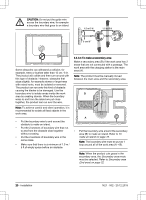
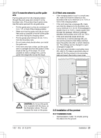
max. 5 cm / 2" max. 5 cm / 2" interference with the signal from the charging station. • Put the charging station in the largest open section of the work area. • Put the charging station in an area without an irrigation system. • Put the charging station in an area with protection from the sun. • If the charging station is installed on an island, make sure to connect the guide wire to the island. Refer to To make an island on page 19. • Put the power supply in an area with a roof and protection from the sun and rain. • Put the power supply in an area with good airflow. • Use a residual-current device (RCD) when you connect the power supply to the power outlet. Low-voltage cables of different lengths are available as accessories. 3.4.3 To examine where to put the boundary wire CAUTION: If the work area is adjacent to water bodies, slopes, precipices or a public road, the boundary wire must have a protective wall. The wall must be minimum 15 cm / 6 in. in height. CAUTION: Do not let the product operate on gravel. 3.4.2 To examine where to put the power supply WARNING: Do not cut or extend the low-voltage cable. There is a risk of electrical shock. CAUTION: Make sure that the blades on the product do not cut the lowvoltage cable. CAUTION: Do not put the low-voltage cable in a coil or below the charging station plate. The coil causes CAUTION: Do not make sharp bends when you install the boundary wire. CAUTION: For careful operation without noise, isolate all obstacles such as trees, roots and stones. The boundary wire should be put as a loop around the work area. Sensors in the product senses when the product approaches the boundary wire, and the product selects another direction. To make the connection easier between the guide wire and the boundary wire, it is recommended to make an eyelet where the guide wire will be connected. Make the eyelet with approximately 20 cm / 8 in. of the boundary wire. 1427 - 002 - 20.12.2019 Installation - 17
-
 1
1 -
2
-
3
-
4
-
5
-
6
-
7
-
8
-
9
-
10
-
11
-
 12
12 -
 13
13 -
 14
14 -
 15
15 -
 16
16 -
 17
17 -
 18
18 -
 19
19 -
 20
20 -
 21
21 -
 22
22 -
23
-
24
-
25
-
26
-
27
-
28
-
29
-
30
-
31
-
32
-
33
-
34
-
35
-
36
-
37
-
38
-
39
-
40
-
41
-
42
-
43
-
44
-
45
-
46
-
47
-
48
-
49
-
50
-
51
-
52
-
53
-
54
-
55
-
56
-
57
-
58
-
59
-
60
-
61
-
62
-
63
-
64
 |
 |
