Husqvarna XciteZ380 Owner Manual - Page 23
Tire pressure, To remove and install the front wheels, To adjust the anti-scalp rollers
 |
View all Husqvarna XciteZ380 manuals
Add to My Manuals
Save this manual to your list of manuals |
Page 23 highlights
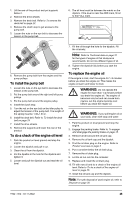
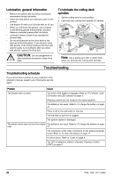
CAUTION: More than 4 turns can cause damage to the product. 4. Start the product. 5. Move the control levers forward fully and operate the product at full throttle. 6. Turn the tracking control on the right side gradually until the product starts to move right. 7. Turn the tracking control on the left side gradually until the product starts to move straight forward. Tire pressure Make sure to have the correct tire pressure on all 4 tires. Refer to Technical data on page 31. To remove and install the front wheels 1. Remove the nut and the bolt to remove the front wheels from the forks. It is not necessary to remove the tube (A). A 2. Install in the opposite sequence. Torque the nut and bolt to 60-85 ft-lbs / 81-115 Nm. CAUTION: Make sure that the tube (A) is installed correctly. If the tube is not installed, the performance will be bad and the life of the wheel is decreased. To adjust the anti-scalp rollers The anti-scalp rollers keep the cutting deck in the correct position on the ground and prevent lawn scalping in most terrain conditions. The anti-scalp rollers can be set in 3 positions for different lengths of grass: • Top position: 1.5-2.5 in. / 38-64 mm grass. • Middle position: 2.5-4 in. / 64-102 mm grass. • Bottom position: 4-5 in. / 102-127 mm grass. 1. Park the product on level ground and stop the engine. 2. Remove the nut, the bolt, the axle and the antiscalp roller. 3. Install the anti-scalp roller in one of the 3 positions. CAUTION: The cutting deck can become damaged if the antiscalp rollers are incorrectly adjusted. The anti-scalp rollers must be approximately 1/4 in. / 6.4 mm from the ground. To adjust the parallelism of the cutting deck This procedure will set the cutting deck in a standard position. 1. Make sure that the tire pressure is correct. Refer to Tire pressure on page 23. 2. Park the product on a level surface. 3. Turn the outer blade tips to align with the cutting deck side to side. WARNING: The blades on the cutting deck are sharp and can cause injury. Use protective gloves. 4. Measure the distance between the ground and the bottom of the blade tip on the discharge side of the cutting deck. Make a note of the distance. 1922 - 002 - 03.11.2022 23
-
 1
1 -
2
-
3
-
4
-
5
-
6
-
7
-
8
-
9
-
10
-
11
-
12
-
13
-
14
-
15
-
16
-
17
-
 18
18 -
 19
19 -
 20
20 -
 21
21 -
 22
22 -
 23
23 -
 24
24 -
 25
25 -
 26
26 -
 27
27 -
 28
28 -
29
-
30
-
31
-
32
-
33
-
34
-
35
-
36
-
37
-
38
-
39
-
40
-
41
-
42
-
43
-
44
-
45
-
46
-
47
-
48
-
49
-
50
-
51
-
52
-
53
-
54
-
55
-
56
-
57
-
58
-
59
-
60
-
61
-
62
-
63
-
64
-
65
-
66
-
67
-
68
-
69
-
70
-
71
-
72
-
73
-
74
-
75
-
76
-
77
-
78
-
79
-
80
-
81
-
82
-
83
-
84
-
85
-
86
-
87
-
88
-
89
-
90
-
91
-
92
-
93
-
94
-
95
-
96
-
97
-
98
-
99
-
100
-
101
-
102
-
103
-
104
-
105
-
106
-
107
-
108
-
109
-
110
-
111
-
112
-
113
-
114
-
115
-
116
 |
 |
