Husqvarna XciteZ380 Owner Manual - Page 4
Control panel overview, To do selections on the display, Message types, Steering controls
 |
View all Husqvarna XciteZ380 manuals
Add to My Manuals
Save this manual to your list of manuals |
Page 4 highlights
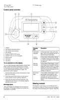
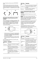
15. Type plate 16. Throttle control Control panel overview 32 17. Oil drain plug 1 9 8 7 4 5 6 1. Display 2. Key switch unlocked position 3. Key switch locked position 4. Key switch 5. Engine START/STOP button 6. ON/OFF button for the headlights 7. Down button 8. OK button 9. Up button To do selections on the display You can select between engine speed, session time, battery status and ambient temperature to show on the display during operation. Refer to Symbols on the control panel and display on page 7 for descriptions of the symbols. 1. Push the OK button on the control panel to open the menu structure. 2. Push the up and down buttons on the control panel until the correct symbol is selected. 3. Push the OK button and wait 5 seconds. The selected symbol shows on the display together with the current value. Message types There are 4 types of messages that can show on the display. A message is shown as a symbol or a combination of symbols. Message type Information message Caution message Warning message Error message Description In the lower right corner of the display. Shows an engaged function or that servicing is necessary. In the center of the display. Shows a condition that is not correct. Refer to Caution messages on the display on page 28. In the center of the display. A warning triangle shows together with an additional symbol if there is a safety warning or the product is defective. Refer to Warning messages on the display on page 29. In the center of the display. A warning triangle shows together with a number. The product cannot be operated until servicing is done. Speak to your Husqvarna servicing dealer. Steering controls The direction of the product is controlled by the 2 control levers. Refer to Product overview on page 3. The right control lever has a PTO (Power Take-Off) 4 1922 - 002 - 03.11.2022
-
 1
1 -
 2
2 -
 3
3 -
 4
4 -
 5
5 -
 6
6 -
 7
7 -
 8
8 -
 9
9 -
 10
10 -
11
-
12
-
13
-
14
-
15
-
16
-
17
-
18
-
19
-
20
-
21
-
22
-
23
-
24
-
25
-
26
-
27
-
28
-
29
-
30
-
31
-
32
-
33
-
34
-
35
-
36
-
37
-
38
-
39
-
40
-
41
-
42
-
43
-
44
-
45
-
46
-
47
-
48
-
49
-
50
-
51
-
52
-
53
-
54
-
55
-
56
-
57
-
58
-
59
-
60
-
61
-
62
-
63
-
64
-
65
-
66
-
67
-
68
-
69
-
70
-
71
-
72
-
73
-
74
-
75
-
76
-
77
-
78
-
79
-
80
-
81
-
82
-
83
-
84
-
85
-
86
-
87
-
88
-
89
-
90
-
91
-
92
-
93
-
94
-
95
-
96
-
97
-
98
-
99
-
100
-
101
-
102
-
103
-
104
-
105
-
106
-
107
-
108
-
109
-
110
-
111
-
112
-
113
-
114
-
115
-
116
 |
 |
