IBM 8668 Hardware Maintenance Manual - Page 48
System board locations, System board option connectors
 |
UPC - 087944723158
View all IBM 8668 manuals
Add to My Manuals
Save this manual to your list of manuals |
Page 48 highlights
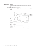
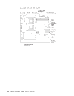
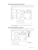
System board locations The illustrations in the following sections show the components on the system board. System board option connectors The following illustration identifies system board connectors for user-installable options. Note: The illustrations in this document might differ slightly from your hardware. Microprocessor 1 (U68) VRM 1 connector (J37) Microprocessor 2 (U69) DIMM 4 (J4) DIMM 3 (J3) DIMM 2 (J2) DIMM 1 (J1) PCI Slot 1 32-bit (J44) PCI Slot 2 64-bit (J41) PCI Slot 3 64-bit (J42) Battery (BH1) PCI Slot 4 64-bit (J29) PCI Slot 5 64-bit (J30) VRM 2 connector (J38) 40 Hardware Maintenance Manual: xSeries 232, Type 8668
-
 1
1 -
2
-
3
-
4
-
5
-
6
-
7
-
8
-
9
-
10
-
11
-
12
-
13
-
14
-
15
-
16
-
17
-
18
-
19
-
20
-
21
-
22
-
23
-
24
-
25
-
26
-
27
-
28
-
29
-
30
-
31
-
32
-
33
-
34
-
35
-
36
-
37
-
38
-
39
-
40
-
41
-
42
-
 43
43 -
 44
44 -
 45
45 -
 46
46 -
 47
47 -
 48
48 -
 49
49 -
 50
50 -
 51
51 -
 52
52 -
 53
53 -
54
-
55
-
56
-
57
-
58
-
59
-
60
-
61
-
62
-
63
-
64
-
65
-
66
-
67
-
68
-
69
-
70
-
71
-
72
-
73
-
74
-
75
-
76
-
77
-
78
-
79
-
80
-
81
-
82
-
83
-
84
-
85
-
86
-
87
-
88
-
89
-
90
-
91
-
92
-
93
-
94
-
95
-
96
-
97
-
98
-
99
-
100
-
101
-
102
-
103
-
104
-
105
-
106
-
107
-
108
-
109
-
110
-
111
-
112
-
113
-
114
-
115
-
116
-
117
-
118
-
119
-
120
-
121
-
122
-
123
-
124
-
125
-
126
-
127
-
128
-
129
-
130
-
131
-
132
-
133
-
134
-
135
-
136
-
137
-
138
-
139
-
140
-
141
-
142
-
143
-
144
-
145
-
146
-
147
-
148
-
149
-
150
-
151
-
152
-
153
-
154
-
155
-
156
-
157
-
158
-
159
-
160
-
161
-
162
-
163
-
164
-
165
-
166
-
167
-
168
-
169
-
170
-
171
-
172
-
173
-
174
-
175
-
176
-
177
-
178
 |
 |

System board locations
The illustrations in the following sections show the components on the system
board.
System board option connectors
The following illustration identifies system board connectors for user-installable
options.
Note:
The illustrations in this document might differ slightly from your hardware.
DIMM 4 (J4)
DIMM 3 (J3)
DIMM 2 (J2)
DIMM 1 (J1)
PCI Slot 1
32-bit (J44)
PCI Slot 2
64-bit (J41)
PCI Slot 3
64-bit (J42)
PCI Slot 4
64-bit (J29)
PCI Slot 5
64-bit (J30)
Battery
(BH1)
Microprocessor 1
(U68)
Microprocessor 2
(U69)
VRM 1 connector (J37)
VRM 2 connector (J38)
40
Hardware Maintenance Manual: xSeries 232, Type 8668