IBM 8668 Hardware Maintenance Manual - Page 82
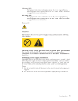
Hot-swap power supply removal, Attention, Important
 |
UPC - 087944723158
View all IBM 8668 manuals
Add to My Manuals
Save this manual to your list of manuals |
Page 82 highlights
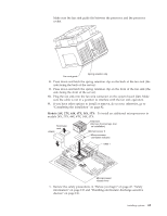
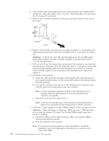
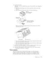
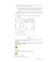
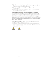
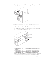
Filler panel Power supply Power supply handle (in open position) Cable-restraint bracket To install a hot-swap power supply: 1. Remove the filler panel from the empty power-supply bay by inserting your finger into the depression on the filler panel and pulling it away from the server. Save the filler panel in case you remove the power supply at a later time. Attention: During typical operation, each power-supply bay must have either a power supply or filler panel installed for proper cooling. 2. Install the power supply in the bay: a. Place the handle on the power supply in the open position (that is, perpendicular to the power supply) and slide the power supply into the chassis. b. Gently close the handle to seat the power supply in the bay. 3. Plug the power cord into the power cord connector located on the rear of the power supply. 4. Route the power cord through the cable-restraint bracket. 5. Plug the power cord into a properly grounded electrical outlet. 6. Verify that the dc power light and ac power light on the power supply are lit, indicating that the power supply is operating correctly. 7. If you have other options to install or remove, do so now. Hot-swap power supply removal If you have a hot-swap power-supply backplane and have installed power supplies, you normally have power redundancy and hot-swappability. However, if the load on your server requires the capacity of all installed power supplies, you do not have redundancy or hot-swappability and must turn off the server before removing any of your power supplies. Important: If you do not have power redundancy, and you remove a power supply while the system is running, your system will immediately power off. To remove a power supply: 1. Check the Information light operation information panel on the front of the server. If on, check the NON (nonredundant) LED (CR24) on the diagnostic panel on the system board. 74 Hardware Maintenance Manual: xSeries 232, Type 8668
-
 1
1 -
2
-
3
-
4
-
5
-
6
-
7
-
8
-
9
-
10
-
11
-
12
-
13
-
14
-
15
-
16
-
17
-
18
-
19
-
20
-
21
-
22
-
23
-
24
-
25
-
26
-
27
-
28
-
29
-
30
-
31
-
32
-
33
-
34
-
35
-
36
-
37
-
38
-
39
-
40
-
41
-
42
-
43
-
44
-
45
-
46
-
47
-
48
-
49
-
50
-
51
-
52
-
53
-
54
-
55
-
56
-
57
-
58
-
59
-
60
-
61
-
62
-
63
-
64
-
65
-
66
-
67
-
68
-
69
-
70
-
71
-
72
-
73
-
74
-
75
-
76
-
 77
77 -
 78
78 -
 79
79 -
 80
80 -
 81
81 -
 82
82 -
 83
83 -
 84
84 -
 85
85 -
 86
86 -
 87
87 -
88
-
89
-
90
-
91
-
92
-
93
-
94
-
95
-
96
-
97
-
98
-
99
-
100
-
101
-
102
-
103
-
104
-
105
-
106
-
107
-
108
-
109
-
110
-
111
-
112
-
113
-
114
-
115
-
116
-
117
-
118
-
119
-
120
-
121
-
122
-
123
-
124
-
125
-
126
-
127
-
128
-
129
-
130
-
131
-
132
-
133
-
134
-
135
-
136
-
137
-
138
-
139
-
140
-
141
-
142
-
143
-
144
-
145
-
146
-
147
-
148
-
149
-
150
-
151
-
152
-
153
-
154
-
155
-
156
-
157
-
158
-
159
-
160
-
161
-
162
-
163
-
164
-
165
-
166
-
167
-
168
-
169
-
170
-
171
-
172
-
173
-
174
-
175
-
176
-
177
-
178
 |
 |
