IBM 8668 Hardware Maintenance Manual - Page 80
Filler panels, Power supply bay 1
 |
UPC - 087944723158
View all IBM 8668 manuals
Add to My Manuals
Save this manual to your list of manuals |
Page 80 highlights
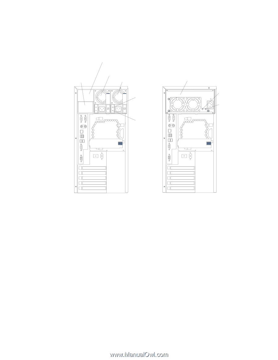
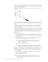
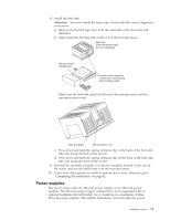
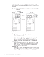
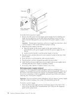
supplies hot-swappable. Each power supply has two status indicators; see the following illustration for information about the status indicators and power-supply bay locations. Note: The illustrations in this document might differ slightly from your hardware. Power supply bay 3 Filler panel Power supply bay 2 Power supply bay 1 Power supply DC power LED (green) DC power LED (green) DC AC GOOD GOOD AC power LED (green) AC power LED (green) Two 250-watt configuration 385-watt configuration Filler panels To maintain proper airflow, keep filler panels in place on empty power-supply bays as shown. Power supply bay 1 Servers utilizing the 250-watt power supply configuration come with a power supply installed in this bay. LED PS1 on the system board diagnostic panel refers to this power supply. See "System board LED locations" on page 45 for more information about the diagnostic panel. Power supply bay 2 Depending on model, the server may come with a power supply installed in this bay. LED PS2 on the system board diagnostic panel refers to this power supply. See "System board LED locations" on page 45 for more information about the diagnostic panel. Power supply bay 3 If you install an optional power supply in this bay, LED PS3 on the system board diagnostic panel refers to this power supply. See "System board LED locations" on page 45 for more information about the diagnostic panel. 72 Hardware Maintenance Manual: xSeries 232, Type 8668
-
 1
1 -
2
-
3
-
4
-
5
-
6
-
7
-
8
-
9
-
10
-
11
-
12
-
13
-
14
-
15
-
16
-
17
-
18
-
19
-
20
-
21
-
22
-
23
-
24
-
25
-
26
-
27
-
28
-
29
-
30
-
31
-
32
-
33
-
34
-
35
-
36
-
37
-
38
-
39
-
40
-
41
-
42
-
43
-
44
-
45
-
46
-
47
-
48
-
49
-
50
-
51
-
52
-
53
-
54
-
55
-
56
-
57
-
58
-
59
-
60
-
61
-
62
-
63
-
64
-
65
-
66
-
67
-
68
-
69
-
70
-
71
-
72
-
73
-
74
-
 75
75 -
 76
76 -
 77
77 -
 78
78 -
 79
79 -
 80
80 -
 81
81 -
 82
82 -
 83
83 -
 84
84 -
 85
85 -
86
-
87
-
88
-
89
-
90
-
91
-
92
-
93
-
94
-
95
-
96
-
97
-
98
-
99
-
100
-
101
-
102
-
103
-
104
-
105
-
106
-
107
-
108
-
109
-
110
-
111
-
112
-
113
-
114
-
115
-
116
-
117
-
118
-
119
-
120
-
121
-
122
-
123
-
124
-
125
-
126
-
127
-
128
-
129
-
130
-
131
-
132
-
133
-
134
-
135
-
136
-
137
-
138
-
139
-
140
-
141
-
142
-
143
-
144
-
145
-
146
-
147
-
148
-
149
-
150
-
151
-
152
-
153
-
154
-
155
-
156
-
157
-
158
-
159
-
160
-
161
-
162
-
163
-
164
-
165
-
166
-
167
-
168
-
169
-
170
-
171
-
172
-
173
-
174
-
175
-
176
-
177
-
178
 |
 |