IBM 8668 Hardware Maintenance Manual - Page 65
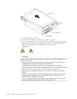
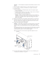
Attention, Connect any needed cables to the adapter.
 |
UPC - 087944723158
View all IBM 8668 manuals
Add to My Manuals
Save this manual to your list of manuals |
Page 65 highlights
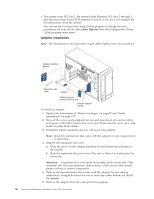
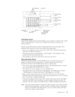
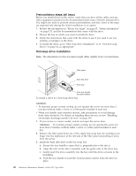
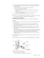
Attention: Avoid touching the components and gold-edge connectors on the adapter. 7. Place the adapter, component-side up, on a flat, static-protective surface. 8. Set any jumpers or switches as described by the adapter manufacturer. 9. Install the adapter: a. If you are installing a full-length adapter, remove the adapter support bracket retaining clip. b. Carefully grasp the adapter by its top edge or upper corners, and align it with the expansion slot on the system board. c. Press the adapter firmly into the expansion slot. Attention: When you install an adapter in the server, be sure that it is completely and correctly seated in the system board connector before you apply power. Incomplete insertion might cause damage to the system board or the adapter. 10. Replace the retaining clip on the adapter support bracket, if you removed it. 11. Align the bottom tabs of the adapter-retention bracket with the holes at the top of the expansion slots, and press the adapter-retention bracket into the holes until it clicks into the locked position. 12. Connect any needed cables to the adapter. Attention: Route cables so that the flow of air from the fans is not blocked. In addition, route any cables plugged into the PCI adapter under adjacent adapters so they are not pinched between the top of the adapter and the top cover. The following illustration shows the rerouting of the SCSI cable if you install a ServeRAID adapter (remove the cable from SCSI connector A (J24) on the system board and connect it to the ServeRAID adapter). Note: The illustrations in this document might differ slightly from your hardware. SCSI connector A SCSI adapter New connector location SCSI cable 13. If you have other options to install or remove, do so now; otherwise, go to "Completing the installation" on page 82. Installing options 57
-
 1
1 -
2
-
3
-
4
-
5
-
6
-
7
-
8
-
9
-
10
-
11
-
12
-
13
-
14
-
15
-
16
-
17
-
18
-
19
-
20
-
21
-
22
-
23
-
24
-
25
-
26
-
27
-
28
-
29
-
30
-
31
-
32
-
33
-
34
-
35
-
36
-
37
-
38
-
39
-
40
-
41
-
42
-
43
-
44
-
45
-
46
-
47
-
48
-
49
-
50
-
51
-
52
-
53
-
54
-
55
-
56
-
57
-
58
-
59
-
 60
60 -
 61
61 -
 62
62 -
 63
63 -
 64
64 -
 65
65 -
 66
66 -
 67
67 -
 68
68 -
 69
69 -
 70
70 -
71
-
72
-
73
-
74
-
75
-
76
-
77
-
78
-
79
-
80
-
81
-
82
-
83
-
84
-
85
-
86
-
87
-
88
-
89
-
90
-
91
-
92
-
93
-
94
-
95
-
96
-
97
-
98
-
99
-
100
-
101
-
102
-
103
-
104
-
105
-
106
-
107
-
108
-
109
-
110
-
111
-
112
-
113
-
114
-
115
-
116
-
117
-
118
-
119
-
120
-
121
-
122
-
123
-
124
-
125
-
126
-
127
-
128
-
129
-
130
-
131
-
132
-
133
-
134
-
135
-
136
-
137
-
138
-
139
-
140
-
141
-
142
-
143
-
144
-
145
-
146
-
147
-
148
-
149
-
150
-
151
-
152
-
153
-
154
-
155
-
156
-
157
-
158
-
159
-
160
-
161
-
162
-
163
-
164
-
165
-
166
-
167
-
168
-
169
-
170
-
171
-
172
-
173
-
174
-
175
-
176
-
177
-
178
 |
 |
