IBM 8668 Hardware Maintenance Manual - Page 62
Removing the bezel (rack model), Working with adapters
 |
UPC - 087944723158
View all IBM 8668 manuals
Add to My Manuals
Save this manual to your list of manuals |
Page 62 highlights
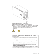
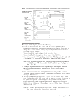
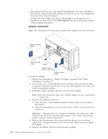
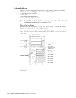
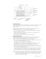
Removing the bezel (rack model) Note: The illustrations in this document might differ slightly from your hardware. Bezel-release lever Bezel To remove the bezel: 1. If you have not done so already, remove the top cover. See "Removing the cover (rack model)" on page 51. 2. Move the blue bezel-release lever in the direction shown in the illustration. 3. Lift the bezel tabs out of the slots and pull the bezel away from the server front. Store the bezel in a safe place. Working with adapters You can install up to five peripheral component interconnect (PCI) adapters in the expansion connectors, called slots, on the system board. Your server comes with an integrated video controller, which is a component on the system board. When you install a video adapter, the server BIOS code automatically disables the integrated video controller. The following illustration shows the location of the PCI expansion slots and system-management connector on the system board. 54 Hardware Maintenance Manual: xSeries 232, Type 8668
-
 1
1 -
2
-
3
-
4
-
5
-
6
-
7
-
8
-
9
-
10
-
11
-
12
-
13
-
14
-
15
-
16
-
17
-
18
-
19
-
20
-
21
-
22
-
23
-
24
-
25
-
26
-
27
-
28
-
29
-
30
-
31
-
32
-
33
-
34
-
35
-
36
-
37
-
38
-
39
-
40
-
41
-
42
-
43
-
44
-
45
-
46
-
47
-
48
-
49
-
50
-
51
-
52
-
53
-
54
-
55
-
56
-
 57
57 -
 58
58 -
 59
59 -
 60
60 -
 61
61 -
 62
62 -
 63
63 -
 64
64 -
 65
65 -
 66
66 -
 67
67 -
68
-
69
-
70
-
71
-
72
-
73
-
74
-
75
-
76
-
77
-
78
-
79
-
80
-
81
-
82
-
83
-
84
-
85
-
86
-
87
-
88
-
89
-
90
-
91
-
92
-
93
-
94
-
95
-
96
-
97
-
98
-
99
-
100
-
101
-
102
-
103
-
104
-
105
-
106
-
107
-
108
-
109
-
110
-
111
-
112
-
113
-
114
-
115
-
116
-
117
-
118
-
119
-
120
-
121
-
122
-
123
-
124
-
125
-
126
-
127
-
128
-
129
-
130
-
131
-
132
-
133
-
134
-
135
-
136
-
137
-
138
-
139
-
140
-
141
-
142
-
143
-
144
-
145
-
146
-
147
-
148
-
149
-
150
-
151
-
152
-
153
-
154
-
155
-
156
-
157
-
158
-
159
-
160
-
161
-
162
-
163
-
164
-
165
-
166
-
167
-
168
-
169
-
170
-
171
-
172
-
173
-
174
-
175
-
176
-
177
-
178
 |
 |
