IBM 8668 Hardware Maintenance Manual - Page 52
Flash boot block recovery jumper, System board switch block, Switch, number, Switch description
 |
UPC - 087944723158
View all IBM 8668 manuals
Add to My Manuals
Save this manual to your list of manuals |
Page 52 highlights
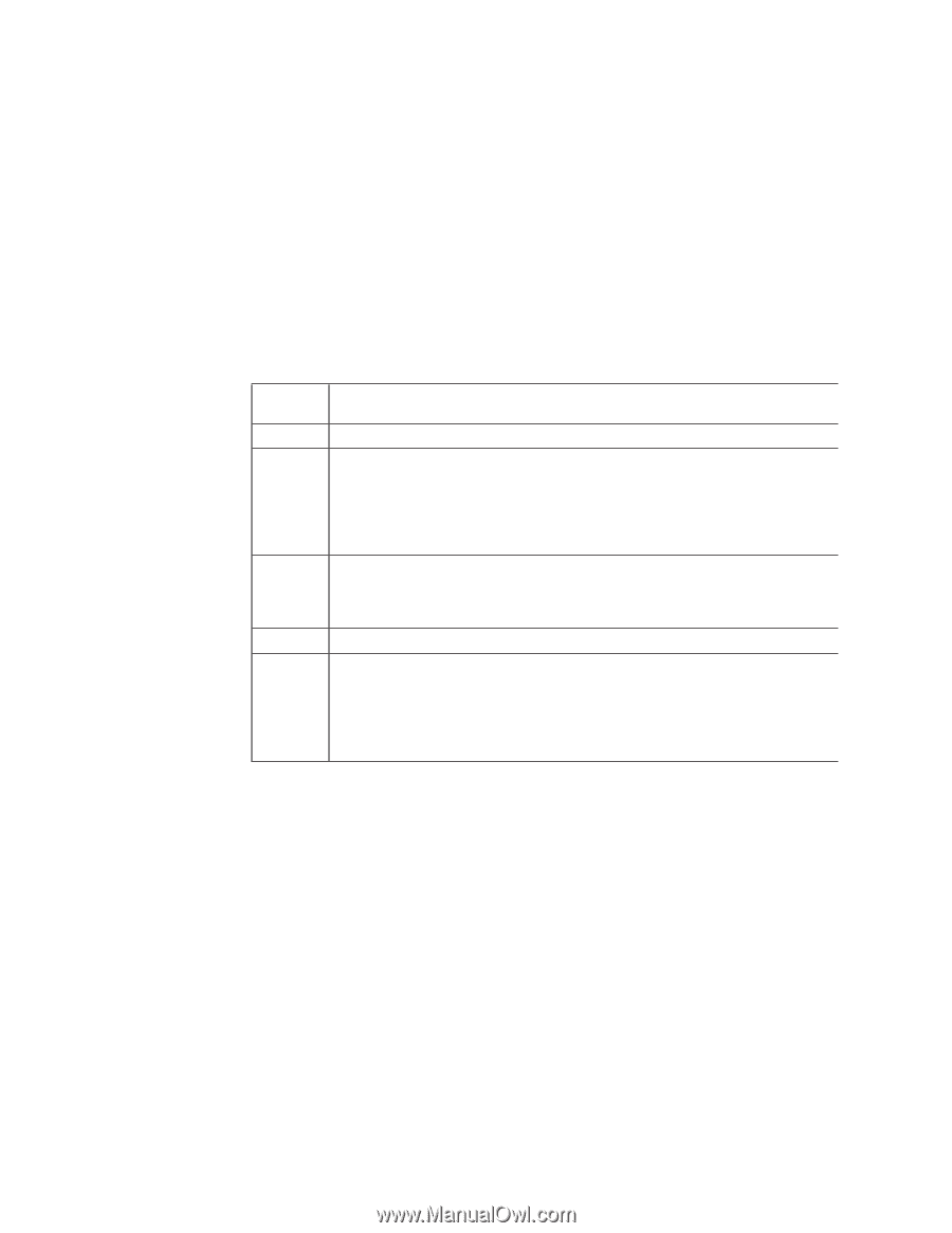
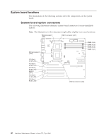
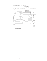
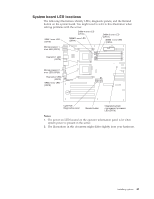
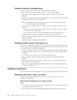
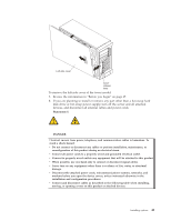
Note: Any jumper blocks on the system board that are not shown in the illustration are reserved. Flash boot block recovery jumper If the BIOS has become damaged, such as from a power failure during a flash update, you can recover the BIOS using the flash boot block recovery jumper and a BIOS flash diskette. See "Recovering BIOS code" on page 17 for information about the flash boot block jumper. System board switch block The switch block contains microswitches 1 through 8. As pictured in this illustration, switch 1 is at the top of the switch block, and switch 8 is at the bottom. The Off position for each switch is the side nearer the microprocessor socket. Table 2. Switches 1-8 Switch Switch description number 1-4 Reserved. 5 Clock frequency selection. The default setting is Off. When this switch is On, the host bus speed is 100 MHz. When this switch is Off, the host bus speed is 133 MHz. The switch should always be set to Off to optimize the system performance. Setting switch 5 to On greatly reduces system performance. 6 Password override. Toggling this switch allows one opportunity to enter the Setup Utility to change or delete the power-on password. 7 Reserved. The default setting is Off. 8 Power-on override. The default setting is Off (disabled). When On, overrides the power-on switch and forces power-on mode. The system will always start without the use of the power-on switch. Note: When power-on switch is set to the On position you cannot power off the server from the front panel. 44 Hardware Maintenance Manual: xSeries 232, Type 8668
-
 1
1 -
2
-
3
-
4
-
5
-
6
-
7
-
8
-
9
-
10
-
11
-
12
-
13
-
14
-
15
-
16
-
17
-
18
-
19
-
20
-
21
-
22
-
23
-
24
-
25
-
26
-
27
-
28
-
29
-
30
-
31
-
32
-
33
-
34
-
35
-
36
-
37
-
38
-
39
-
40
-
41
-
42
-
43
-
44
-
45
-
46
-
 47
47 -
 48
48 -
 49
49 -
 50
50 -
 51
51 -
 52
52 -
 53
53 -
 54
54 -
 55
55 -
 56
56 -
 57
57 -
58
-
59
-
60
-
61
-
62
-
63
-
64
-
65
-
66
-
67
-
68
-
69
-
70
-
71
-
72
-
73
-
74
-
75
-
76
-
77
-
78
-
79
-
80
-
81
-
82
-
83
-
84
-
85
-
86
-
87
-
88
-
89
-
90
-
91
-
92
-
93
-
94
-
95
-
96
-
97
-
98
-
99
-
100
-
101
-
102
-
103
-
104
-
105
-
106
-
107
-
108
-
109
-
110
-
111
-
112
-
113
-
114
-
115
-
116
-
117
-
118
-
119
-
120
-
121
-
122
-
123
-
124
-
125
-
126
-
127
-
128
-
129
-
130
-
131
-
132
-
133
-
134
-
135
-
136
-
137
-
138
-
139
-
140
-
141
-
142
-
143
-
144
-
145
-
146
-
147
-
148
-
149
-
150
-
151
-
152
-
153
-
154
-
155
-
156
-
157
-
158
-
159
-
160
-
161
-
162
-
163
-
164
-
165
-
166
-
167
-
168
-
169
-
170
-
171
-
172
-
173
-
174
-
175
-
176
-
177
-
178
 |
 |