IBM 8835 Hardware Maintenance Manual - Page 15
connectors, Notes, drive, status, Power-cord, connector
 |
UPC - 000435158314
View all IBM 8835 manuals
Add to My Manuals
Save this manual to your list of manuals |
Page 15 highlights
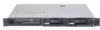
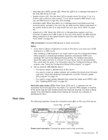
Rear view v Hard disk drive (HDD) activity LED: When this LED is lit, it indicates that either of the hard disk drives is in use. v System locator LED: Use this blue LED to visually locate the server if it is in a location with numerous other servers. If your server supports IBM Director, you can use IBM Director to light this LED remotely. v Information LED: When this LED is lit, it indicates that a noncritical event has occurred and is recorded in the error log. An LED near the failing component on the system board is also lit to help isolate the error (see "Error LEDs" on page 20). v System-error LED: When this LED is lit, it indicates that a system error has occurred. A system-error LED is also on the rear of the server. An LED near the failing component on the system board is also lit to help isolate the error (see "Error LEDs" on page 20). USB connectors: Connect USB devices to these connectors. Notes: 1. If you want to attach a keyboard or mouse to this server, you must use a USB keyboard or a USB mouse. After installing a USB keyboard, you might need to use the Configuration/Setup Utility program to enable keyboardless operation and prevent POST error message 301 from being displayed during startup. For detailed information about this option and how to connect it to your server, see the documentation that comes with the option. For information about the Configuration/Setup Utility program, see "Using the Configuration/Setup Utility program" on page 9. 2. Use an external USB diskette drive if: v You want to attach a diskette drive to this server. v You need to create an update diskette that contains the latest server firmware code (see "Using the baseboard management controller firmware update utility program" on page 11). v You need to create update diskettes that contain the latest server BIOS code (see "Updating BIOS code" on page 21). Hard disk drive status LEDs: When these LEDs are lit, it indicates that the associated SCSI hard disk drive has failed. If an optional RAID adapter is installed in the server and the LED flashes slowly (one flash per second), the drive is being rebuilt. If the LED flashes rapidly (three flashes per second), the controller is identifying the drive. The following illustration shows the connectors and LEDs on the rear of the server. Activity LEDs Link LEDs System-error LED Power-cord connector Serial connector Video USB connectors connector Power-on LED Gigabit Ethernet 1 connector (LAN1) Gigabit Ethernet 2 connector (LAN2) Power-cord connector: Connect the power cord to this connector. Chapter 1. General information 5
-
 1
1 -
2
-
3
-
4
-
5
-
6
-
7
-
8
-
9
-
 10
10 -
 11
11 -
 12
12 -
 13
13 -
 14
14 -
 15
15 -
 16
16 -
 17
17 -
 18
18 -
 19
19 -
 20
20 -
21
-
22
-
23
-
24
-
25
-
26
-
27
-
28
-
29
-
30
-
31
-
32
-
33
-
34
-
35
-
36
-
37
-
38
-
39
-
40
-
41
-
42
-
43
-
44
-
45
-
46
-
47
-
48
-
49
-
50
-
51
-
52
-
53
-
54
-
55
-
56
-
57
-
58
-
59
-
60
-
61
-
62
-
63
-
64
-
65
-
66
-
67
-
68
-
69
-
70
-
71
-
72
-
73
-
74
-
75
-
76
-
77
-
78
-
79
-
80
-
81
-
82
-
83
-
84
-
85
-
86
-
87
-
88
-
89
-
90
-
91
-
92
-
93
-
94
-
95
-
96
-
97
-
98
-
99
-
100
-
101
-
102
-
103
-
104
-
105
-
106
-
107
-
108
-
109
-
110
-
111
-
112
-
113
-
114
-
115
-
116
-
117
-
118
-
119
-
120
-
121
-
122
-
123
-
124
-
125
-
126
-
127
-
128
-
129
-
130
-
131
-
132
-
133
-
134
-
135
-
136
-
137
-
138
-
139
-
140
-
141
-
142
-
143
-
144
-
145
-
146
-
147
-
148
-
149
-
150
-
151
-
152
-
153
-
154
-
155
-
156
-
157
-
158
-
159
-
160
-
161
-
162
-
163
-
164
 |
 |
