IBM 8863 Service Guide - Page 137
Power-supply, structure
 |
UPC - 000435474667
View all IBM 8863 manuals
Add to My Manuals
Save this manual to your list of manuals |
Page 137 highlights
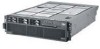
8. Lift the guide out of the server. To install a PCI-X adapter guide, complete the following steps: 1. Align the two tabs on the PCI-X adapter guide with the two slots on the chassis. 2. Set the guide firmly into place and turn the quarter-turn fasteners to secure the guide. 3. Reconnect the cables that pass through the PCI-X adapter guide and route the cables through the routing feature of the guide. 4. Install the adapters and dividers. 5. When replacing the dividers, make sure that the tabs on the bottom of the dividers rest in the holes in the bottom of the metal section of the guide and the tabs on the top of the dividers engage the plastic retainer section of the guide. 6. Lower the latch mechanism. 7. Replace the top cover. 8. Reconnect external cables and power cords. Power-supply structure To remove the power-supply structure, complete the following steps. Latches Alignment tabs Handle Alignment pins 1. Read the safety information that begins on page vii, and "Handling static-sensitive devices" on page 100. Attention: Static electricity that is released to internal server components when the server is powered-on might cause the server to halt, which could result in the loss of data. To avoid this potential problem, always use an electrostatic-discharge wrist strap or other grounding system when working inside the server with the power on. 2. Turn off the server and peripheral devices, and disconnect the power cords and all external cables necessary to replace the device. 3. Remove the top cover. 4. Remove the memory cards (see "Removing and replacing a memory card" on page 111). 5. Remove the power supplies (see "Hot-swap power supply" on page 106). Chapter 4. Removing and replacing server components 121
-
 1
1 -
2
-
3
-
4
-
5
-
6
-
7
-
8
-
9
-
10
-
11
-
12
-
13
-
14
-
15
-
16
-
17
-
18
-
19
-
20
-
21
-
22
-
23
-
24
-
25
-
26
-
27
-
28
-
29
-
30
-
31
-
32
-
33
-
34
-
35
-
36
-
37
-
38
-
39
-
40
-
41
-
42
-
43
-
44
-
45
-
46
-
47
-
48
-
49
-
50
-
51
-
52
-
53
-
54
-
55
-
56
-
57
-
58
-
59
-
60
-
61
-
62
-
63
-
64
-
65
-
66
-
67
-
68
-
69
-
70
-
71
-
72
-
73
-
74
-
75
-
76
-
77
-
78
-
79
-
80
-
81
-
82
-
83
-
84
-
85
-
86
-
87
-
88
-
89
-
90
-
91
-
92
-
93
-
94
-
95
-
96
-
97
-
98
-
99
-
100
-
101
-
102
-
103
-
104
-
105
-
106
-
107
-
108
-
109
-
110
-
111
-
112
-
113
-
114
-
115
-
116
-
117
-
118
-
119
-
120
-
121
-
122
-
123
-
124
-
125
-
126
-
127
-
128
-
129
-
130
-
131
-
 132
132 -
 133
133 -
 134
134 -
 135
135 -
 136
136 -
 137
137 -
 138
138 -
 139
139 -
 140
140 -
 141
141 -
 142
142 -
143
-
144
-
145
-
146
-
147
-
148
-
149
-
150
-
151
-
152
-
153
-
154
-
155
-
156
-
157
-
158
-
159
-
160
-
161
-
162
-
163
-
164
-
165
-
166
-
167
-
168
-
169
-
170
-
171
-
172
 |
 |
