IBM HS40 Hardware Maintenance Manual
IBM HS40 - BladeCenter - 8839 Manual
 |
UPC - 000435160188
View all IBM HS40 manuals
Add to My Manuals
Save this manual to your list of manuals |
IBM HS40 manual content summary:
- IBM HS40 | Hardware Maintenance Manual - Page 1
ERserver BladeCenter HS40 Type 8839 Hardware Maintenance Manual and Troubleshooting Guide - IBM HS40 | Hardware Maintenance Manual - Page 2
- IBM HS40 | Hardware Maintenance Manual - Page 3
ERserver BladeCenter HS40 Type 8839 Hardware Maintenance Manual and Troubleshooting Guide - IBM HS40 | Hardware Maintenance Manual - Page 4
on page 149. Fourth Edition (May 2004) Note: The most recent version of this document is available at http://www.ibm.com/pc/support. © Copyright International Business Machines Corporation 2004. All rights reserved. US Government Users Restricted Rights - Use, duplication or disclosure restricted by - IBM HS40 | Hardware Maintenance Manual - Page 5
intended for trained servicers who are familiar with IBM BladeCenter products. See the parts listing in Chapter 7, "Parts listing, Type 8839," on page 105 to determine if the component being replaced is a customer replaceable unit (CRU) or a FRU. If a problem with the HS40 blade server is suspected - IBM HS40 | Hardware Maintenance Manual - Page 6
iv BladeCenter HS40 Type 8839: Hardware Maintenance Manual and Troubleshooting Guide - IBM HS40 | Hardware Maintenance Manual - Page 7
Contents About this manual iii Important safety information iii Online support iii Chapter 1. Introduction 1 Related publications 2 Features and specifications 4 BladeCenter HS40 specifications for non-NEBS/ETSI environments . . . . . 4 BladeCenter HS40 specifications for NEBS/ETSI - IBM HS40 | Hardware Maintenance Manual - Page 8
-related system shutdown 101 Hard disk drive checkout 101 Undetermined problems 101 Problem determination tips 102 Chapter 7. Parts listing, Type 8839 105 Appendix A. Getting help and technical assistance 107 vi BladeCenter HS40 Type 8839: Hardware Maintenance Manual and Troubleshooting Guide - IBM HS40 | Hardware Maintenance Manual - Page 9
and information from the World Wide Web 108 Software service and support 108 Hardware service and support 108 Appendix B. Safety information 109 General safety 109 Electrical safety 110 Safety inspection guide 111 Handling electrostatic discharge-sensitive devices 112 Grounding requirements - IBM HS40 | Hardware Maintenance Manual - Page 10
viii BladeCenter HS40 Type 8839: Hardware Maintenance Manual and Troubleshooting Guide - IBM HS40 | Hardware Maintenance Manual - Page 11
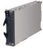
1. Introduction The IBM BladeCenter HS40 Type 8839 blade server is based on the IBM Enterprise X-Architecture™ technologies1. The HS40 blade server is a double-width blade-model server and can be installed in an IBM BladeCenter Type 8677 unit or IBM BladeCenter T Eserver Eserver Types 8720 - IBM HS40 | Hardware Maintenance Manual - Page 12
Maintenance Manual and Troubleshooting Guide is provided in Portable Document Format (PDF). It contains information to help you solve a problem yourself or to provide helpful information to a service technician. 2 BladeCenter HS40 Type 8839: Hardware Maintenance Manual and Troubleshooting Guide - IBM HS40 | Hardware Maintenance Manual - Page 13
unit. v BladeCenter Type 8677 Hardware Maintenance Manual and Eserver Troubleshooting Guide This publication contains the information to help you solve BladeCenter problems yourself and information for service technicians. v BladeCenter Type 8677 Rack Installation Instructions Eserver This - IBM HS40 | Hardware Maintenance Manual - Page 14
blade server must provide USB support for the blade server to recognize and use the keyboard, mouse, CD-ROM drive, and diskette drive. The BladeCenter unit uses USB for internal communications with these devices. 4 BladeCenter HS40 Type 8839: Hardware Maintenance Manual and Troubleshooting Guide - IBM HS40 | Hardware Maintenance Manual - Page 15
features and specifications of the BladeCenter T HS40 Type 8839 blade server operating in a NEBS/ETSI environment. Note: Power, cooling, removable-media drives, external ports, and advanced system management are provided by the IBM BladeCenter T Type Eserver 8720. Microprocessor: Supports up - IBM HS40 | Hardware Maintenance Manual - Page 16
is restored (if the blade server is configured through the BladeCenter management module to do so). v You can turn on the blade server remotely by means of the service processor in the BladeCenter management module. 6 BladeCenter HS40 Type 8839: Hardware Maintenance Manual and Troubleshooting Guide - IBM HS40 | Hardware Maintenance Manual - Page 17
shut down properly. Turning off the blade server When you turn off the blade server, it is still connected to power through the BladeCenter unit. The blade server can respond to requests from the service processor, such as a remote request to turn on the blade server. To remove all power from the - IBM HS40 | Hardware Maintenance Manual - Page 18
the keyboard and mouse. The BladeCenter unit uses USB for internal communication with these devices. When you are running an operating system that does not have USB device drivers, the keyboard responds very slowly. 8 BladeCenter HS40 Type 8839: Hardware Maintenance Manual and Troubleshooting Guide - IBM HS40 | Hardware Maintenance Manual - Page 19
on LED: This green LED indicates the power status of the blade server in the following manner: v Flashing rapidly - The service processor on the blade server is handshaking with the BladeCenter management module. v Flashing slowly - The blade server has power but is not turned on. v Lit continuously - IBM HS40 | Hardware Maintenance Manual - Page 20
10 BladeCenter HS40 Type 8839: Hardware Maintenance Manual and Troubleshooting Guide - IBM HS40 | Hardware Maintenance Manual - Page 21
Director products, depending on your blade server, see the IBM BladeCenter Planning and Installation Guide or the Eserver IBM BladeCenter T Planning and Installation Guide. You can obtain the Eserver planning guides from http://www.ibm.com/pc/support/. Using the Configuration/Setup Utility - IBM HS40 | Hardware Maintenance Manual - Page 22
Web interface. You can enable the blade server to run without a diskette drive or keyboard. The Extensible Firmware Interface (EFI) start option should not be selected for any of the startup or boot device fields. 12 BladeCenter HS40 Type 8839: Hardware Maintenance Manual and Troubleshooting Guide - IBM HS40 | Hardware Maintenance Manual - Page 23
Module User's Guide on the IBM BladeCenter T Documentation CD for information and instructions. v Save Settings Select this choice to save the changes you have made in the settings and exit from the Configuration/Setup Utility program. v Restore Settings Chapter 2. Configuring the blade server 13 - IBM HS40 | Hardware Maintenance Manual - Page 24
and installation program that is designed for your IBM blade server. The ServerGuide program detects the blade server model and hardware options that are installed and your SCSI controller with RAID capabilities 14 BladeCenter HS40 Type 8839: Hardware Maintenance Manual and Troubleshooting Guide - IBM HS40 | Hardware Maintenance Manual - Page 25
supported on all blade server models. The ServerGuide program requires a supported IBM blade server that is associated with an enabled startable (bootable) CD-ROM drive only) v Checks the microcode (firmware) levels of a ServeRAID adapter and program provides the device drivers that are required for - IBM HS40 | Hardware Maintenance Manual - Page 26
-system installation instructions from the IBM Support Web page: 1. Go to http://www.ibm.com/pc/support/. 2. In the Download section, click Downloads & drivers. 3. On the "Downloads and drivers" page, in the Brand field, select Servers. 4. In the Family field, select BladeCenter HS40. 5. Click - IBM HS40 | Hardware Maintenance Manual - Page 27
firmware. Download the latest firmware for your blade server service processor from the IBM Support Web site at http://www.ibm.com/pc/support/. Use the BladeCenter management-module Web interface to flash the service processor. The Web interface is described in the IBM BladeCenter Type 8677 - IBM HS40 | Hardware Maintenance Manual - Page 28
, the Ethernet controller that you enabled is associated with the switch module in I/O-module bay 1. The other Ethernet controller in the blade server is associated with the switch module in I/O-module bay 2. 18 BladeCenter HS40 Type 8839: Hardware Maintenance Manual and Troubleshooting Guide - IBM HS40 | Hardware Maintenance Manual - Page 29
for your blade server through a serial over LAN (SOL) connection. See the IBM Eserver BladeCenter Management Module Command-Line Interface User's Guide and the IBM BladeCenter Serial Over LAN Setup Guide for information and Eserver instructions. Chapter 2. Configuring the blade server 19 - IBM HS40 | Hardware Maintenance Manual - Page 30
20 BladeCenter HS40 Type 8839: Hardware Maintenance Manual and Troubleshooting Guide - IBM HS40 | Hardware Maintenance Manual - Page 31
are stored in the upgradeable read-only memory (ROM). IBM Director provides a real-time diagnostics program that tests the major components of the blade server while the server operating system is running. The diagnostics can be downloaded from http://www.ibm.com/pc/support/. v When you run the - IBM HS40 | Hardware Maintenance Manual - Page 32
of this document, the IBM Director CD does not come with the BladeCenter T unit. If you have the BladeCenter T unit, see the IBM BladeCenter HS40 Type 8839 Installation and User's Guide for Eserver more information. 22 BladeCenter HS40 Type 8839: Hardware Maintenance Manual and Troubleshooting Guide - IBM HS40 | Hardware Maintenance Manual - Page 33
Manager after initializing the main window of the AF. The SEL Manager Add-In provides services to view the SEL stored on the server management storage device of a server. The SEL Manager provides support to perform the following functions: v Examine all SEL entries stored in the non-volatile storage - IBM HS40 | Hardware Maintenance Manual - Page 34
v Examine SEL entries from a previously stored file. v Save the SEL entries to a file. v Clear the SEL entries from the non-volatile storage area. 24 BladeCenter HS40 Type 8839: Hardware Maintenance Manual and Troubleshooting Guide - IBM HS40 | Hardware Maintenance Manual - Page 35
can run the SSU SEL Viewer from the Resource CD that comes with the blade server. The latest SSU utility image can be downloaded from the IBM Support Web site at http://www.ibm.com/eserver/support/. If you download the latest image of the SSU utility, complete the following steps: 1. Create diskette - IBM HS40 | Hardware Maintenance Manual - Page 36
that was being tested when the blade server stopped. b. The keyboard and mouse (pointing device) tests assume that a keyboard and mouse are attached to the BladeCenter and that the blade server controls them. 26 BladeCenter HS40 Type 8839: Hardware Maintenance Manual and Troubleshooting Guide - IBM HS40 | Hardware Maintenance Manual - Page 37
can view server configuration information (such as system configuration, memory contents, and device drivers) by processor board and I/O board. You might need to refer to these illustrations when solving problems with the blade server. You need to remove the blade server from the BladeCenter - IBM HS40 | Hardware Maintenance Manual - Page 38
The following illustration shows the LEDs on the processor board. Microprocessor 2 error LED (DS5H4) Microprocessor 1 error LED ( (DS6G2) DIMM 8 error LED (DS6H1) Microprocessor socket 3 Microprocessor socket 4 28 BladeCenter HS40 Type 8839: Hardware Maintenance Manual and Troubleshooting Guide - IBM HS40 | Hardware Maintenance Manual - Page 39
Processor blade server from the BladeCenter unit. The LEDs will remain lit for as long as you press the button, to a maximum of 25 seconds. Use the table at "Light path diagnostics" on page 86 to help determine the cause of the error and the action you should take. Memory errors If a memory problem - IBM HS40 | Hardware Maintenance Manual - Page 40
BIOS flash diskette into the diskette drive. 7. Restart the blade server. The server begins the power-on self-test (POST). 8. Select 1 - Update POST/BIOS from the menu that contains various flash (update) options. 30 BladeCenter HS40 Type 8839: Hardware Maintenance Manual and Troubleshooting Guide - IBM HS40 | Hardware Maintenance Manual - Page 41
the blade server in the BladeCenter unit; then restart the blade server. The blade server starts. Statement 21 CAUTION: Hazardous energy is present when the blade server is connected to the power source. Always replace the blade cover before installing the blade server. Clearing CMOS memory Complete - IBM HS40 | Hardware Maintenance Manual - Page 42
32 BladeCenter HS40 Type 8839: Hardware Maintenance Manual and Troubleshooting Guide - IBM HS40 | Hardware Maintenance Manual - Page 43
hot-swap components.) See the instructions for removing or installing a specific hot-swap component for any additional procedures that you might have to perform before you remove or install the component. v For a list of supported options for your blade server, go to http://www.ibm.com/pc/us/compat - IBM HS40 | Hardware Maintenance Manual - Page 44
. Blade expansion connector terminator Air baffle Microprocessor heat-sink (up to 4) Microprocessor (up to 4) Microprocessor heat-sink filler (up to 3) Bezel Top cover I/O board DIMM (up to 8) Processor board 34 BladeCenter HS40 Type 8839: Hardware Maintenance Manual and Troubleshooting Guide - IBM HS40 | Hardware Maintenance Manual - Page 45
components The following illustration shows the components on the I/O board. J8H1 connector J4H1 connector Battery I/O expansion option 1 connectors I/O expansion option 2 connectors Flex-cable connectors (to processor board) Blade expansion connector (J3A1) Chapter 4. Installing options 35 - IBM HS40 | Hardware Maintenance Manual - Page 46
processor board and I/O board. You need to remove the blade server from the BladeCenter unit, open the cover, and press one of the Light path diagnostics buttons to light any error LEDs that were lit during blade server BladeCenter HS40 Type 8839: Hardware Maintenance Manual and Troubleshooting Guide - IBM HS40 | Hardware Maintenance Manual - Page 47
The following illustration shows the LEDs on the I/O board. Secondary IDE error LED (DS6H1) Primary IDE error LED (DS2H1) Board error (DS7A2) Processor board error LED (DS8A2) Light path diagnostics button (S8A1) Light path diagnostics LED (green) (DS8A1) BMC error LED (DS7B1) NMI error LED ( - IBM HS40 | Hardware Maintenance Manual - Page 48
. Note: If you start the blade server from the backup page because the primary BIOS page has become damaged, you need to flash the primary BIOS code. See "Recovering the BIOS code" on page 30 for instructions. 38 BladeCenter HS40 Type 8839: Hardware Maintenance Manual and Troubleshooting Guide - IBM HS40 | Hardware Maintenance Manual - Page 49
, do not operate the BladeCenter unit without either a blade server, expansion unit, or filler blade installed in each blade bay for more than 1 minute for the BladeCenter unit and 20 minutes for the BladeCenter T unit. v Note the bay number. Reinstalling a blade server into a different bay than - IBM HS40 | Hardware Maintenance Manual - Page 50
blade server cover: 1. Review the safety information beginning on page 109 and "Installation guidelines" on page 33. 2. Carefully lay the blade server down on a flat, nonconductive surface, with the cover side up. 40 BladeCenter HS40 Type 8839: Hardware Maintenance Manual and Troubleshooting Guide - IBM HS40 | Hardware Maintenance Manual - Page 51
blade server and lift the cover open, as shown in the illustration. 4. Lay the cover flat, or lift it from the blade server. Statement 21: CAUTION: Hazardous energy is present when the blade server is connected to the power source. Always replace the blade cover before installing the blade server - IBM HS40 | Hardware Maintenance Manual - Page 52
33. 2. Open the blade server cover (see "Opening the blade server cover" on page 40 for instructions), and lift it off the blade server. 3. Press the the blade server. 6. Store the bezel assembly in a safe place. 42 BladeCenter HS40 Type 8839: Hardware Maintenance Manual and Troubleshooting Guide - IBM HS40 | Hardware Maintenance Manual - Page 53
the blade server, and remove the blade server from the BladeCenter unit. See "Removing the blade server from the BladeCenter unit" on page 39 for instructions. 3. Carefully lay the blade server on a flat, static-protective surface. 4. Open the blade server cover (see "Opening the blade server cover - IBM HS40 | Hardware Maintenance Manual - Page 54
DIMM pairs must be installed in the blade server. The hot spare memory feature is enabled using the Configuration/Setup Utility program (see "Configuration/Setup Utility menu choices" on page 12 for information). 44 BladeCenter HS40 Type 8839: Hardware Maintenance Manual and Troubleshooting Guide - IBM HS40 | Hardware Maintenance Manual - Page 55
the blade server cover" on page 40 for instructions) and lift it off the blade server. 5. Press the I/O-tray release and rotate the I/O-tray open, as shown in the illustration. The I/O tray is hinged and will support itself in the open position. 6. Locate the DIMM connectors on the processor board - IBM HS40 | Hardware Maintenance Manual - Page 56
, sometimes called a microprocessor baffle. v The microprocessor speeds are automatically set for this blade server; therefore, you do not need to set any microprocessor frequency-selection jumpers or switches. 46 BladeCenter HS40 Type 8839: Hardware Maintenance Manual and Troubleshooting Guide - IBM HS40 | Hardware Maintenance Manual - Page 57
off the blade server, and remove the blade server from the BladeCenter unit. See "Removing the blade server from the BladeCenter unit" on page 39 for instructions. 3. Carefully lay the blade server on a flat, nonconductive surface. 4. Open the blade server cover (see "Opening the blade server cover - IBM HS40 | Hardware Maintenance Manual - Page 58
microprocessor, microprocessor socket, and processor board. Lever closed or Lever fully open Lever closed Lever fully open d. Center the microprocessor over the microprocessor the microprocessor in the socket. 48 BladeCenter HS40 Type 8839: Hardware Maintenance Manual and Troubleshooting Guide - IBM HS40 | Hardware Maintenance Manual - Page 59
thermal grease becomes contaminated, contact your service technician. b. Align and place BladeCenter unit both support the I/O expansion card network-interface type. For example, if you add an Ethernet expansion card to your blade server, the modules in switch-module bays 3 and 4 on the BladeCenter - IBM HS40 | Hardware Maintenance Manual - Page 60
raised hook on the tray; then, gently pivot the wide end of the card into the I/O expansion card connectors, as shown in the illustration. 50 BladeCenter HS40 Type 8839: Hardware Maintenance Manual and Troubleshooting Guide - IBM HS40 | Hardware Maintenance Manual - Page 61
Instructions that comes with the optional expansion unit. Installing a SCSI storage expansion unit Attention: You must install a SCSI storage expansion unit that is specified for use with the IBM HS40 Type 8839 blade server. Two types of SCSI storage expansion units are available for BladeCenter - IBM HS40 | Hardware Maintenance Manual - Page 62
, and remove the blade server from the BladeCenter unit (see "Removing the blade server from the BladeCenter unit" on page 39 for instructions). 3. Carefully lay the blade server on a flat, nonconductive surface. 52 BladeCenter HS40 Type 8839: Hardware Maintenance Manual and Troubleshooting Guide - IBM HS40 | Hardware Maintenance Manual - Page 63
the blade server cover (see "Opening the blade server cover" on page 40 for instructions), and lift it off the blade server. Cover pins Blade cover Blade-cover release Air baffle Blade-cover release b. Store the cover in a safe place. 5. Locate the blade expansion connector on the processor board - IBM HS40 | Hardware Maintenance Manual - Page 64
screws are through the holes in the air baffle. Air baffle Microprocessor 1 and 4 heat sink captive mounting screws 8. Install the SCSI storage expansion unit: 54 BladeCenter HS40 Type 8839: Hardware Maintenance Manual and Troubleshooting Guide - IBM HS40 | Hardware Maintenance Manual - Page 65
Attention: Install only a SCSI storage expansion unit that is specified for use with the IBM HS40 Type 8839 blade server. Compatible SCSI storage expansion units do not have a shield, as shown in the following illustration. Use SCSI storage expansion unit with no shield Do not - IBM HS40 | Hardware Maintenance Manual - Page 66
present in all four power bays. 10. Turn on the blade server. 11. If you have not already done so, install the LSI SCSI device drivers for your operating system. LSI device drivers are on the ServerGuide Setup and 56 BladeCenter HS40 Type 8839: Hardware Maintenance Manual and Troubleshooting Guide - IBM HS40 | Hardware Maintenance Manual - Page 67
CD that comes with the BladeCenter unit. You can also get the latest version of the drivers from the IBM Support Web site at http://www.ibm.com/pc/support/. With the storage expansion unit installed on your blade server, you can install up to two hot-swap SCSI hard disk drives in the expansion unit - IBM HS40 | Hardware Maintenance Manual - Page 68
disk drive activity LED is flashing, the hard disk drive is being accessed. See the documentation that comes with the expansion unit for information about configuring the expansion unit and SCSI hard disk drives. 58 BladeCenter HS40 Type 8839: Hardware Maintenance Manual and Troubleshooting Guide - IBM HS40 | Hardware Maintenance Manual - Page 69
BladeCenter HS40 blade server in a BladeCenter Type 8677 unit. These illustrations might differ slightly from your hardware. However, this installation process is the same regardless of the BladeCenter unit. Hard disk drive Blade server instructions. Note: In the U. S., call 1-800-IBM-4333 - IBM HS40 | Hardware Maintenance Manual - Page 70
"Removing the blade server from the BladeCenter unit" on page 39 for instructions). 4. Open the blade server cover (see "Opening the blade server cover" on page 40 for instructions) and lift it off the blade server. 60 BladeCenter HS40 Type 8839: Hardware Maintenance Manual and Troubleshooting Guide - IBM HS40 | Hardware Maintenance Manual - Page 71
. b. As you slide it under the battery clip, press the battery down into the socket until the battery retainer secures it in place. 8. Close the blade server cover (see "Closing the blade server cover" on page 63). Statement 21: Chapter 4. Installing options 61 - IBM HS40 | Hardware Maintenance Manual - Page 72
on the blade server flashes slowly before pressing the power-control button on a blade server. Installing the blade server bezel assembly Complete the following steps to install the blade server bezel assembly. 62 BladeCenter HS40 Type 8839: Hardware Maintenance Manual and Troubleshooting Guide - IBM HS40 | Hardware Maintenance Manual - Page 73
Connect the control-panel cable to the control-panel connector on the processor board. Control-panel connector Control-panel cable 3. Insert the tabs snap into place. Closing the blade server cover Important: The blade server cannot be inserted into the BladeCenter unit until the cover is installed - IBM HS40 | Hardware Maintenance Manual - Page 74
that the slots at the rear slide down onto the pins at the rear of the blade server, as shown in the illustration. 6. Pivot the cover to the closed position as shown in the illustration, until it clicks into place. 64 BladeCenter HS40 Type 8839: Hardware Maintenance Manual and Troubleshooting Guide - IBM HS40 | Hardware Maintenance Manual - Page 75
on a BladeCenter HS40 blade server in a BladeCenter Type 8677 unit. These illustrations might differ slightly from your hardware. However, this installation process is the same regardless of the BladeCenter unit. Blade server Filler blade Complete the following steps to install a blade server in the - IBM HS40 | Hardware Maintenance Manual - Page 76
bezel just below the blade server, as shown in the following illustration. CD CD CD User label Important: Do not place the label on the blade server or block the ventilation holes on the blade server in any way. 66 BladeCenter HS40 Type 8839: Hardware Maintenance Manual and Troubleshooting Guide - IBM HS40 | Hardware Maintenance Manual - Page 77
blade server in the BladeCenter unit, you must configure the blade server with the blade server Configuration/Setup Utility and install the blade server operating system. See "Updating your blade server configuration" and the IBM BladeCenter HS40 Type 8839 Installation and Eserver User's Guide - IBM HS40 | Hardware Maintenance Manual - Page 78
to upgrade the operating system to support SMP. For more information, see IBM BladeCenter HS40 Type 8839 Installation and User's Guide and Eserver your operating-system documentation. Input/output connectors and devices The input/output connectors that are available to your blade server are - IBM HS40 | Hardware Maintenance Manual - Page 79
server, and remove the blade server from the BladeCenter unit (see "Removing the blade server from the BladeCenter unit" on page 39). 2. Carefully lay the blade server on a flat, nonconductive surface. 3. Open the blade server cover (see "Opening the blade server cover" on page 40 for instructions - IBM HS40 | Hardware Maintenance Manual - Page 80
. Failure to do so might result in permanent damage to the microprocessor, microprocessor socket, and system board. Lever closed Lever fully open Lever closed 70 BladeCenter HS40 Type 8839: Hardware Maintenance Manual and Troubleshooting Guide Lever fully open - IBM HS40 | Hardware Maintenance Manual - Page 81
9. Lift the microprocessor out of the socket. To install a microprocessor, see "Installing an additional microprocessor" on page 46 for instructions. Attention: If you are not installing a replacement microprocessor in socket 2, you must reinstall the microprocessor baffle in that socket. Chapter 5. - IBM HS40 | Hardware Maintenance Manual - Page 82
with the latest firmware or restore the pre-existing firmware that the customer provides on a diskette or CD image. Note: v Read "Installation guidelines" on page 33. v Read the safety notices beginning on page 109. 72 BladeCenter HS40 Type 8839: Hardware Maintenance Manual and Troubleshooting Guide - IBM HS40 | Hardware Maintenance Manual - Page 83
the following steps to remove the processor board: 1. Shut down the operating system, and turn off the blade server (see "Turning off the blade server" on page 7). 2. Remove the blade server from the BladeCenter unit (see "Removing the blade server from the BladeCenter unit" on page 39). 3. Remove - IBM HS40 | Hardware Maintenance Manual - Page 84
connecting the I/O board to the processor board. 6. Remove all components (see the appropriate installation instructions and reverse the steps), and place them on a static-protective surface for reinstallation. 74 BladeCenter HS40 Type 8839: Hardware Maintenance Manual and Troubleshooting Guide - IBM HS40 | Hardware Maintenance Manual - Page 85
7. Remove the other seven screws that secure the I/O board to the blade chassis, and put the screws in a safe place. 8. Pull the I/O board carefully out of the blade chassis. Reverse these steps to install the replacement I/O board. Chapter 5. Service replaceable units 75 - IBM HS40 | Hardware Maintenance Manual - Page 86
76 BladeCenter HS40 Type 8839: Hardware Maintenance Manual and Troubleshooting Guide - IBM HS40 | Hardware Maintenance Manual - Page 87
locating failing or failed components in the HS40 Type 8839 blade server. Notes: 1. Check the configuration before you replace a FRU. Configuration problems can cause false errors and symptoms. 2. For IBM devices not supported by this index, refer to the manual for that device. 3. Always start with - IBM HS40 | Hardware Maintenance Manual - Page 88
and no video (System See "Undetermined problems" on page 101. error LED is OFF) No beep and no video (System See "Diagnosing problems using the light path diagnostics feature" on page Attention LED is ON) 27. 78 BladeCenter HS40 Type 8839: Hardware Maintenance Manual and Troubleshooting Guide - IBM HS40 | Hardware Maintenance Manual - Page 89
8839," on page 105 to determine which components should be replaced by a field service 1. I/O board 2. Processor board 0044 (DMA drive - ATAPI incompatible) Primary master hard disk drive 0057 (Secondary master drive - ATAPI incompatible) Secondary master hard disk drive 005D ATA drive - IBM HS40 | Hardware Maintenance Manual - Page 90
program, and enable the processor retest. 2. Microprocessor 4. 8140 (Microprocessor 1 failed FRB-3 timer) 1. Run the Configuration/Setup Utility program, and enable the processor retest. 2. Microprocessor 1. 80 BladeCenter HS40 Type 8839: Hardware Maintenance Manual and Troubleshooting Guide - IBM HS40 | Hardware Maintenance Manual - Page 91
7, "Parts listing, Type 8839," on page 105 to determine which components should be replaced by a field service technician. Error code/symptom FRU/action 8141 (Microprocessor 2 failed FRB-3 timer) 1. Run the Configuration/Setup Utility program, and enable the processor retest. 2. Microprocessor - IBM HS40 | Hardware Maintenance Manual - Page 92
. 2. Microprocessor 3. 3. Processor board. Microprocessor 4 internal error (IERR) 1. Run the Configuration/Setup Utility program, and enable the microprocessor retest. 2. Microprocessor 4. 3. Processor board. 82 BladeCenter HS40 Type 8839: Hardware Maintenance Manual and Troubleshooting Guide - IBM HS40 | Hardware Maintenance Manual - Page 93
microprocessor 4 2. System board 165-060-000 (Service Processor: ASM may 1. Rerun the diagnostic test. be busy) 2. Fix other error conditions that may be keeping ASM busy. Refer to the error log and diagnostic panel. 3. Power down the blade server, and reseat it in the chassis. 4. System - IBM HS40 | Hardware Maintenance Manual - Page 94
, or ROM.) 2. System board. 167-300-XXX ISMP: Failed (ISMP indicates failure in self test.) 1. Remove and reinstall the blade server in the BladeCenter unit. 2. Reflash or update firmware for ISMP. 3. I/O board. 84 BladeCenter HS40 Type 8839: Hardware Maintenance Manual and Troubleshooting Guide - IBM HS40 | Hardware Maintenance Manual - Page 95
8839," on page 105 to determine which components should be replaced by a field service technician. Error code/symptom FRU/action 167-400-001 ISMP: Failed (ISMP failed to communicate with I/O board.) I/O board 167-400-002 ISMP: Failed 1. Processor DIMM. b. Rerun memory diagnostic for the failing - IBM HS40 | Hardware Maintenance Manual - Page 96
server cover, reinsert the blade server in the system chassis, and then restart the blade server. (See "Removing the blade server from the BladeCenter unit" on page 39 for instructions). 2. Replace the I/O board. 86 BladeCenter HS40 Type 8839: Hardware Maintenance Manual and Troubleshooting Guide - IBM HS40 | Hardware Maintenance Manual - Page 97
the blade server cover, reinsert the blade server in the BladeCenter unit, and then restart the blade server. 2. Check the system error log for information about the error. 3. Replace the processor board and the I/O board. See "Processor board" on page 72 and "I/O board" on page 74 for instructions - IBM HS40 | Hardware Maintenance Manual - Page 98
you You can now safely switch ownership of the media tray to another blade server. have not safely stopped the drives before switching ownership of the CD-ROM drive, diskette drive, and USB port (media tray).) 88 BladeCenter HS40 Type 8839: Hardware Maintenance Manual and Troubleshooting Guide - IBM HS40 | Hardware Maintenance Manual - Page 99
working Note: See Chapter 7, "Parts listing, Type 8839," on page 105 to determine which components should be replaced by a field service technician. Hard disk drive problems Symptom FRU/action Not all drives are recognized by the hard disk drive diagnostic test (Fixed Disk test). 1. Remove the - IBM HS40 | Hardware Maintenance Manual - Page 100
Management module on the BladeCenter unit; see the IBM BladeCenter Type 8677 Hardware Maintenance Manual and Troubleshooting Guide on the IBM BladeCenter Documentation CD. Mouse function lost during Red Hat installation. If, while installing Red Hat Linux 7.3 to a blade server, you or someone else - IBM HS40 | Hardware Maintenance Manual - Page 101
and disable hot spare memory; then, run the diagnostics test again. Note: See Chapter 7, "Parts listing, Type 8839," on page 105 to determine which components should be replaced by a field service technician. Microprocessor problems Symptom FRU/action The blade server emits a 1. Make sure that - IBM HS40 | Hardware Maintenance Manual - Page 102
some memory instructions. If you still cannot find the problem, try using the monitor with another blade server. If the problem persists, see the IBM BladeCenter Type 8677 Hardware Maintenance Manual and Troubleshooting Guide on the IBM BladeCenter Documentation CD. 92 BladeCenter HS40 Type 8839 - IBM HS40 | Hardware Maintenance Manual - Page 103
on page 105 to determine which components should be replaced by a field service technician. Option problems Symptom FRU/action An IBM option that was just installed does not work. 1. Make sure that: v The option is designed for the server (see the ServerProven list on the World Wide Web at http - IBM HS40 | Hardware Maintenance Manual - Page 104
during BIOS POST and power-control button does not work, remove the blade server from the bay and reseat it. 2. If the problem remains or if you are using an ACPI-aware operating system, suspect the system board. 94 BladeCenter HS40 Type 8839: Hardware Maintenance Manual and Troubleshooting Guide - IBM HS40 | Hardware Maintenance Manual - Page 105
must be replaced by an IBM field service technician. ServerGuide problems Symptom FRU/action Setup and Installation CD will not start. v Make sure that the server supports the ServerGuide program and has a startable (bootable) CD-ROM (or DVD-ROM) drive. v If the startup (boot) sequence - IBM HS40 | Hardware Maintenance Manual - Page 106
correctly. See the IBM BladeCenter Type 8677 Hardware Maintenance Manual and Troubleshooting Guide on the IBM BladeCenter Documentation CD for details. v The settings in the switch module are appropriate for the blade server (settings in the switch module are blade-specific). If you installed - IBM HS40 | Hardware Maintenance Manual - Page 107
, Type 8839," on page 105 to determine which components should be replaced by a field service technician. Message Action BSE +12V over recommended voltage 1. Check BladeCenter power (see IBM BladeCenter Type 8677 Hardware Maintenance Manual and Troubleshooting Guide). 2. Reseat blade storage - IBM HS40 | Hardware Maintenance Manual - Page 108
blade storage expansion option. System Power Good fault 1. Check BladeCenter power (see IBM BladeCenter Type 8677 Hardware Maintenance Manual and Troubleshooting Guide). 2. Reseat blade server. 3. Replace blade server. 98 BladeCenter HS40 Type 8839: Hardware Maintenance Manual and Troubleshooting - IBM HS40 | Hardware Maintenance Manual - Page 109
8839," on page 105 to determine which components should be replaced by a field service technician. Message Action VRM Power Good fault 1. Check BladeCenter power (see IBM BladeCenter Type 8677 Hardware Maintenance Manual and Troubleshooting Guide). 2. Reseat blade server. 3. Replace blade server - IBM HS40 | Hardware Maintenance Manual - Page 110
8839," on page 105 to determine which components should be replaced by a field service technician. Message Action System under recommended voltage for +1.5v. 1. Check BladeCenter power (see IBM BladeCenter Type 8677 Hardware Maintenance Manual and Troubleshooting Guide). 2. Reseat blade server - IBM HS40 | Hardware Maintenance Manual - Page 111
over temperature, blade server powering down See IBM BladeCenter Type 8677 Hardware Maintenance Manual and Troubleshooting Guide. Hard disk drive checkout Note: See Chapter 7, "Parts listing, Type 8839," on page 105 to determine which components should be replaced by a field service technician - IBM HS40 | Hardware Maintenance Manual - Page 112
or hard disk upgrades v Failure symptom: - Does the server fail the diagnostics tests? - What, when, where, single, or multiple servers? - Is the failure repeatable? - Has this configuration ever worked? 102 BladeCenter HS40 Type 8839: Hardware Maintenance Manual and Troubleshooting Guide - IBM HS40 | Hardware Maintenance Manual - Page 113
code level v Operating system software - Type and version level Note: To eliminate confusion, blade servers are considered identical only if they: v Are the exact machine type and model v ″working″ and ″non-working″ servers will often lead to problem resolution. Chapter 6. Symptom-to-FRU index 103 - IBM HS40 | Hardware Maintenance Manual - Page 114
104 BladeCenter HS40 Type 8839: Hardware Maintenance Manual and Troubleshooting Guide - IBM HS40 | Hardware Maintenance Manual - Page 115
Chapter 7. Parts listing, Type 8839 This parts listing supports the HS40 Type 8839 blade server models 21X, 31X, 41X,51X, 61X, 71X, and 6TX. 1 12 11 2 10 3 9 8 4 7 6 5 Index 1 2 3 3 3 3 4 5 6 6 7 7 7 7 7 7 8 Note: Field replaceable units (FRUs) should be serviced only by qualified field - IBM HS40 | Hardware Maintenance Manual - Page 116
Blade cover (all models) Fibre channel adapter tray (optional) Fibre channel card (optional) Gigabit Ethernet daughter card System service Light pipe, hard disk drive LEDs (2) v Screw, mobile hard disk drive tray, M3 x # BladeCenter HS40 Type 8839: Hardware Maintenance Manual and Troubleshooting Guide - IBM HS40 | Hardware Maintenance Manual - Page 117
Manual and Troubleshooting Guide on the IBM xSeries Documentation CD or in the IntelliStation Hardware Maintenance Manual at the IBM Support Web site. v Go to the IBM Support Web site at http://www.ibm.com/pc/support/ to check for technical information, hints, tips, and new device drivers - IBM HS40 | Hardware Maintenance Manual - Page 118
800-IBM-SERV (1-800-426-7378). In the U.S. and Canada, hardware service and support is available 24 hours a day, 7 days a week. In the U.K., these services are available Monday through Friday, from 9 a.m. to 6 p.m. 108 BladeCenter HS40 Type 8839: Hardware Maintenance Manual and Troubleshooting Guide - IBM HS40 | Hardware Maintenance Manual - Page 119
are designed to help you isolate problems. They are written with the assumption that you have model-specific training on all computers, or that you are familiar with the computers, functions, terminology, and service information provided in this manual. The following section contains the safety - IBM HS40 | Hardware Maintenance Manual - Page 120
modems before you open the server covers, unless instructed otherwise in the installation and instructions are in the safety sections of maintenance information. Use extreme care when measuring high voltages. 110 BladeCenter HS40 Type 8839: Hardware Maintenance Manual and Troubleshooting Guide - IBM HS40 | Hardware Maintenance Manual - Page 121
users and service personnel from injury. This guide addresses only -IBM features or options not covered by this inspection guide. If any unsafe conditions are present, you must determine how serious the apparent hazard could be and whether you can continue without first correcting the problem - IBM HS40 | Hardware Maintenance Manual - Page 122
IBM alterations. Use good judgment as to the safety of any non-IBM server, the part, the work mat, and the person handling the part are all at the same charge. Notes: 1. Use product-specific the specific service BladeCenter HS40 Type 8839: Hardware Maintenance Manual and Troubleshooting Guide - IBM HS40 | Hardware Maintenance Manual - Page 123
Korean v Spanish Important: All caution and danger statements in this IBM documentation begin with a number. This number is used to cross read all caution and danger statements before performing any of the instructions. Statement 1 DANGER Electrical current from power, telephone and communication - IBM HS40 | Hardware Maintenance Manual - Page 124
use only IBM Part Number laser products (such as CD-ROMs, DVD-ROM drives, fiber optic devices, or transmitters) are installed, to hazardous laser radiation. There are no serviceable parts inside the device. v Use of BladeCenter HS40 Type 8839: Hardware Maintenance Manual and Troubleshooting Guide - IBM HS40 | Hardware Maintenance Manual - Page 125
than 82 kg (180 lbs.) on top of rack-mounted devices. Statement 20 CAUTION: To avoid personal injury, before lifting the unit, remove all the blades to reduce the weight. Statement 21 Appendix B. Safety information 115 - IBM HS40 | Hardware Maintenance Manual - Page 126
CAUTION: Hazardous energy is present when the blade server is connected to the power source. Always replace the blade cover before installing the blade server. 116 BladeCenter HS40 Type 8839: Hardware Maintenance Manual and Troubleshooting Guide - IBM HS40 | Hardware Maintenance Manual - Page 127
Importante: Todas as instruções de cuidado e perigo da IBM documentation começam com um número. Este número é utilizado para fazer referência cruzada de uma instrução de cuidado ou perigo no idioma inglês com - IBM HS40 | Hardware Maintenance Manual - Page 128
889-8986, para obter informações sobre como enviar a bateria pelo correio para a IBM. Instrução 3 PRECAUCIÓN: Quando produtos a laser (unidades de CD-ROM, unidades íticos, e evite exposição direta ao raio. 118 BladeCenter HS40 Type 8839: Hardware Maintenance Manual and Troubleshooting Guide - IBM HS40 | Hardware Maintenance Manual - Page 129
Instrução 4 ≥18 kg (39.7 lb) ≥32 kg (70.5 lb) ≥55 kg (121.2 lb) CUIDADO: Ao levantar a máquina, faça-o com segurança. Instrução 5 CUIDADO: Os botões Liga/Desliga localizados no dispositivo e na fonte de alimentação não desligam a corrente elétrica fornecida ao dispositivo. O dispositivo também pode - IBM HS40 | Hardware Maintenance Manual - Page 130
Instrução 21 CUIDADO: A energia é uma ameaça quando a låmina estiver conectada à fonte de alimentação. Sempre substitua a cobertura da låmina antes de efetuar a instalação. 120 BladeCenter HS40 Type 8839: Hardware Maintenance Manual and Troubleshooting Guide - IBM HS40 | Hardware Maintenance Manual - Page 131
Appendix B. Safety information 121 - IBM HS40 | Hardware Maintenance Manual - Page 132
122 BladeCenter HS40 Type 8839: Hardware Maintenance Manual and Troubleshooting Guide - IBM HS40 | Hardware Maintenance Manual - Page 133
Appendix B. Safety information 123 - IBM HS40 | Hardware Maintenance Manual - Page 134
124 BladeCenter HS40 Type 8839: Hardware Maintenance Manual and Troubleshooting Guide - IBM HS40 | Hardware Maintenance Manual - Page 135
Appendix B. Safety information 125 - IBM HS40 | Hardware Maintenance Manual - Page 136
126 BladeCenter HS40 Type 8839: Hardware Maintenance Manual and Troubleshooting Guide - IBM HS40 | Hardware Maintenance Manual - Page 137
Appendix B. Safety information 127 - IBM HS40 | Hardware Maintenance Manual - Page 138
es dans la bibliothèque IBM documentation sont précédées d' aux systèmes de télécommunication et aux modems (sauf instruction contraire mentionnée dans les procédures d'installation et de les câbles des unités. 128 BladeCenter HS40 Type 8839: Hardware Maintenance Manual and Troubleshooting Guide - IBM HS40 | Hardware Maintenance Manual - Page 139
Notice n° 2 ATTENTION: Remplacez la pile au lithium usagée par une pile de référence identique exclusivement - voir la référence IBM - ou par une pile équivalente recommandée par le fabricant. Si votre système est doté d'un module contenant une pile au lithium, vous devez le - IBM HS40 | Hardware Maintenance Manual - Page 140
és montées en armoire. Notice n° 20 ATTENTION: Pour éviter tout risque de blessure, retirez tous les Serveurs lame de l'unité avant de la soulever. 130 BladeCenter HS40 Type 8839: Hardware Maintenance Manual and Troubleshooting Guide - IBM HS40 | Hardware Maintenance Manual - Page 141
Notice n° 21 ATTENTION: Un courant électrique dangereux est présent lorsque le Serveur lame est connecté á une source d'alimentation. Remettez toujours en place le carter du Serveur lame avant d'installer le Serveur lame. Appendix B. Safety information 131 - IBM HS40 | Hardware Maintenance Manual - Page 142
Wichtig: Alle Sicherheitshinweise in dieser IBM documentation beginnen mit einer Nummer. Diese Nummer verweist auf einen Steckdose lösen. 3. Signalkabel von Anschlußbuchsen lösen. 4. Alle Kabel von Einheiten lösen. 132 BladeCenter HS40 Type 8839: Hardware Maintenance Manual and Troubleshooting Guide - IBM HS40 | Hardware Maintenance Manual - Page 143
Hinweis 2 ACHTUNG: Eine verbrauchte Batterie nur durch eine Batterie mit der IBM Teilenummer 33F8354 oder durch eine vom Hersteller empfohlene Batterie ersetzen. Wenn Ihr System ein Modul mit einer Lithium-Batterie enthält, ersetzen Sie es immer - IBM HS40 | Hardware Maintenance Manual - Page 144
Vorderseite des Servers und dem Betriebsspannungsschalter am Netzteil wird die Stromversorgung für den Server nicht unterbrochen. Der Server könnte auch Anheben der Einheit zur Verringerung des Gewichts alle Blades. 134 BladeCenter HS40 Type 8839: Hardware Maintenance Manual and Troubleshooting Guide - IBM HS40 | Hardware Maintenance Manual - Page 145
Hinweis 21 ACHTUNG: Wenn das Blade an eine Stromquelle angeschlossen ist, besteht die Gefahr eines Stromschlags. Bringen Sie die Abdeckung der Blades immer an, bevor Sie sie installieren. Appendix B. Safety information 135 - IBM HS40 | Hardware Maintenance Manual - Page 146
avvisi di attenzione e di pericolo riportati nella pubblicazione IBM documentation iniziano con un numero. Questo numero viene utilizzato elettriche. 4. Rimuovere tutti i cavi dalle unità. 5. ACCENDERE le unità. 136 BladeCenter HS40 Type 8839: Hardware Maintenance Manual and Troubleshooting Guide - IBM HS40 | Hardware Maintenance Manual - Page 147
si sostituisce la batteria al litio, utilizzare solo una batteria IBM con numero parte 33F8354 o batterie dello stesso tipo o controlli, regolazioni o l'esecuzione di procedure non descritti nel presente manuale possono provocare l'esposizione a radiazioni pericolose. PERICOLO Alcuni prodotti laser - IBM HS40 | Hardware Maintenance Manual - Page 148
peso. Avviso 21 ATTENZIONE: Quando la lama è collegata alla sorgente elettrica è presente una tensione pericolosa. Sostituire sempre il coperchio della lama prima di installarla. 138 BladeCenter HS40 Type 8839: Hardware Maintenance Manual and Troubleshooting Guide - IBM HS40 | Hardware Maintenance Manual - Page 149
Appendix B. Safety information 139 - IBM HS40 | Hardware Maintenance Manual - Page 150
140 BladeCenter HS40 Type 8839: Hardware Maintenance Manual and Troubleshooting Guide - IBM HS40 | Hardware Maintenance Manual - Page 151
Appendix B. Safety information 141 - IBM HS40 | Hardware Maintenance Manual - Page 152
142 BladeCenter HS40 Type 8839: Hardware Maintenance Manual and Troubleshooting Guide - IBM HS40 | Hardware Maintenance Manual - Page 153
Appendix B. Safety information 143 - IBM HS40 | Hardware Maintenance Manual - Page 154
144 BladeCenter HS40 Type 8839: Hardware Maintenance Manual and Troubleshooting Guide - IBM HS40 | Hardware Maintenance Manual - Page 155
Importante: Todas las declaraciones de precauciín de esta IBM documentation empiezan con un número. Dicho número se emplea para establecer una referencia cruzada de una declaraciín de precauciín o peligro en inglés con las versiones - IBM HS40 | Hardware Maintenance Manual - Page 156
sustituir la batería de litio, utilice únicamente el número de pieza 33F8354 de IBM o cualquier tipo de batería equivalente que recomiende el fabricante. Si el sistema ípticos; evite la exposiciín directa al rayo. 146 BladeCenter HS40 Type 8839: Hardware Maintenance Manual and Troubleshooting Guide - IBM HS40 | Hardware Maintenance Manual - Page 157
Declaración 4 ≥18 kg ≥32 kg ≥55 kg PRECAUCIÓN: Tome medidas de seguridad al levantar el producto. Declaración 5 PRECAUCIÓN: El botín de control de alimentaciín del dispositivo y el interruptor de alimentaciín de la fuente de alimentaciín no apagan la corriente eléctrica suministrada al - IBM HS40 | Hardware Maintenance Manual - Page 158
Declaración 21 PRECAUCIÓN: Existe energia perigosa quando a låmina está ligada à fonte de alimentação. Substitua sempre a cobertura da låmina antes de instalar a mesma. 148 BladeCenter HS40 Type 8839: Hardware Maintenance Manual and Troubleshooting Guide - IBM HS40 | Hardware Maintenance Manual - Page 159
to evaluate and verify the operation of any non-IBM product, program, or service. IBM may have patents or pending patent applications covering subject license inquiries, in writing, to: IBM Director of Licensing IBM Corporation North Castle Drive Armonk, NY 10504-1785 U.S.A. INTERNATIONAL BUSINESS - IBM HS40 | Hardware Maintenance Manual - Page 160
the internal clock speed of the microprocessor; other factors also affect application performance. CD-ROM drive speeds list the variable read rate. Actual speeds vary and are often less than the maximum possible. 150 BladeCenter HS40 Type 8839: Hardware Maintenance Manual and Troubleshooting Guide - IBM HS40 | Hardware Maintenance Manual - Page 161
of all hard disk drive bays with the largest currently supported drives available from IBM. Maximum memory may require replacement of the standard memory with an optional memory module. IBM makes no representation or warranties regarding non-IBM products and services that are ServerProven, including - IBM HS40 | Hardware Maintenance Manual - Page 162
installed and used in accordance with the instruction manual, may cause harmful interference to radio communications used in order to meet FCC emission limits. IBM is not responsible for any radio or television BladeCenter HS40 Type 8839: Hardware Maintenance Manual and Troubleshooting Guide - IBM HS40 | Hardware Maintenance Manual - Page 163
responsibility for any failure to satisfy the protection requirements resulting from a nonrecommended modification of the product, including the fitting of non-IBM option cards. This product has been tested and found to comply with the limits for Class A Information Technology Equipment according to - IBM HS40 | Hardware Maintenance Manual - Page 164
a maximum of 15 feet in length and a parallel blade, grounding-type attachment plug rated 15 amperes, 125 volts IBM power cords for a specific country or region are usually available only in that country or region. IBM BladeCenter HS40 Type 8839: Hardware Maintenance Manual and Troubleshooting Guide - IBM HS40 | Hardware Maintenance Manual - Page 165
IBM power cord part number 14F0033 14F0051 14F0069 14F0087 1838574 24P6858 34G0232 36L8880 49P2078 49P2110 6952300 Used in these countries and regions Abu Dhabi, Bahrain, Botswana, - IBM HS40 | Hardware Maintenance Manual - Page 166
156 BladeCenter HS40 Type 8839: Hardware Maintenance Manual and Troubleshooting Guide - IBM HS40 | Hardware Maintenance Manual - Page 167
server 11 connectors battery 35 blade expansion 35 I/O expansion option 35 input/output 68 memory 35 microprocessor 35 processor board 35 controller enable or disable Ethernet 12 Ethernet 17 SCSI 52, 57 controller enumeration 18 © Copyright IBM Corp. 2004 cover closing 63 removing 40 D diagnostic - IBM HS40 | Hardware Maintenance Manual - Page 168
NOS installation with ServerGuide 15 without ServerGuide 16 notes, important 150 notices electronic emission 152 FCC, Class A 152 O option installing 33 options problems 93 order of installation memory modules 44 158 BladeCenter HS40 Type 8839: Hardware Maintenance Manual and Troubleshooting Guide - IBM HS40 | Hardware Maintenance Manual - Page 169
15 using 14 service processor features 17 service processor error codes 96 setting BIOS code page jumper 38 password override switch 14 setup with ServerGuide 15 software problems 95 SOL 19 start options 12 starting diagnostic programs 26 starting the blade server 6 startup sequence, setting - IBM HS40 | Hardware Maintenance Manual - Page 170
A notice 152 Universal Serial Bus (USB) problems 95 updating firmware 17 utility Configuration/Setup Utility program 11 PXE boot agent program, using 16 W Web site ServerGuide 14 supported blade server options 33 160 BladeCenter HS40 Type 8839: Hardware Maintenance Manual and Troubleshooting Guide - IBM HS40 | Hardware Maintenance Manual - Page 171
- IBM HS40 | Hardware Maintenance Manual - Page 172
Part Number: 25K8105 Printed in USA (1P) P/N: 25K8105
-
 1
1 -
 2
2 -
 3
3 -
 4
4 -
 5
5 -
 6
6 -
 7
7 -
8
-
9
-
10
-
11
-
12
-
13
-
14
-
15
-
16
-
17
-
18
-
19
-
20
-
21
-
22
-
23
-
24
-
25
-
26
-
27
-
28
-
29
-
30
-
31
-
32
-
33
-
34
-
35
-
36
-
37
-
38
-
39
-
40
-
41
-
42
-
43
-
44
-
45
-
46
-
47
-
48
-
49
-
50
-
51
-
52
-
53
-
54
-
55
-
56
-
57
-
58
-
59
-
60
-
61
-
62
-
63
-
64
-
65
-
66
-
67
-
68
-
69
-
70
-
71
-
72
-
73
-
74
-
75
-
76
-
77
-
78
-
79
-
80
-
81
-
82
-
83
-
84
-
85
-
86
-
87
-
88
-
89
-
90
-
91
-
92
-
93
-
94
-
95
-
96
-
97
-
98
-
99
-
100
-
101
-
102
-
103
-
104
-
105
-
106
-
107
-
108
-
109
-
110
-
111
-
112
-
113
-
114
-
115
-
116
-
117
-
118
-
119
-
120
-
121
-
122
-
123
-
124
-
125
-
126
-
127
-
128
-
129
-
130
-
131
-
132
-
133
-
134
-
135
-
136
-
137
-
138
-
139
-
140
-
141
-
142
-
143
-
144
-
145
-
146
-
147
-
148
-
149
-
150
-
151
-
152
-
153
-
154
-
155
-
156
-
157
-
158
-
159
-
160
-
161
-
162
-
163
-
164
-
165
-
166
-
167
-
168
-
169
-
170
-
171
-
172
 |
 |

BladeCenter
HS40
Type
8839
Hardware
Maintenance
Manual
and
Troubleshooting
Guide
E
Rserver
±²³