IBM HS40 Hardware Maintenance Manual - Page 48
Switches, jumpers, Jumpers
 |
UPC - 000435160188
View all IBM HS40 manuals
Add to My Manuals
Save this manual to your list of manuals |
Page 48 highlights
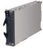
Switches and jumpers The following illustration shows the switches and jumpers on the I/O board. Configuration switch block (S6H1) 3 2 1 BIOS code page jumper (J1E2) Light path diagnostics button (S8A1) Switches Table 1 describes the function of each switch on switch block (S6H1). Table 1. Configuration Switch block (S6H1) Switch number Default value Switch description 1 Off Reserved 2 Off Password disable 3 through 5 Off Reserved Jumpers When the BIOS code page jumper (J1E2) is moved from pins 1 and 2 to pins 2 and 3, you can start the blade server from a backup BIOS page. The default position is pins 1 and 2. See the blade server Hardware Maintenance Manual and Troubleshooting Guide on the IBM BladeCenter Documentation CD for more information. Note: If you start the blade server from the backup page because the primary BIOS page has become damaged, you need to flash the primary BIOS code. See "Recovering the BIOS code" on page 30 for instructions. 38 BladeCenter HS40 Type 8839: Hardware Maintenance Manual and Troubleshooting Guide
-
 1
1 -
2
-
3
-
4
-
5
-
6
-
7
-
8
-
9
-
10
-
11
-
12
-
13
-
14
-
15
-
16
-
17
-
18
-
19
-
20
-
21
-
22
-
23
-
24
-
25
-
26
-
27
-
28
-
29
-
30
-
31
-
32
-
33
-
34
-
35
-
36
-
37
-
38
-
39
-
40
-
41
-
42
-
 43
43 -
 44
44 -
 45
45 -
 46
46 -
 47
47 -
 48
48 -
 49
49 -
 50
50 -
 51
51 -
 52
52 -
 53
53 -
54
-
55
-
56
-
57
-
58
-
59
-
60
-
61
-
62
-
63
-
64
-
65
-
66
-
67
-
68
-
69
-
70
-
71
-
72
-
73
-
74
-
75
-
76
-
77
-
78
-
79
-
80
-
81
-
82
-
83
-
84
-
85
-
86
-
87
-
88
-
89
-
90
-
91
-
92
-
93
-
94
-
95
-
96
-
97
-
98
-
99
-
100
-
101
-
102
-
103
-
104
-
105
-
106
-
107
-
108
-
109
-
110
-
111
-
112
-
113
-
114
-
115
-
116
-
117
-
118
-
119
-
120
-
121
-
122
-
123
-
124
-
125
-
126
-
127
-
128
-
129
-
130
-
131
-
132
-
133
-
134
-
135
-
136
-
137
-
138
-
139
-
140
-
141
-
142
-
143
-
144
-
145
-
146
-
147
-
148
-
149
-
150
-
151
-
152
-
153
-
154
-
155
-
156
-
157
-
158
-
159
-
160
-
161
-
162
-
163
-
164
-
165
-
166
-
167
-
168
-
169
-
170
-
171
-
172
 |
 |
