Intel BX80571E5300 Data Sheet - Page 21
Signaling Specifications
 |
UPC - 735858204996
View all Intel BX80571E5300 manuals
Add to My Manuals
Save this manual to your list of manuals |
Page 21 highlights
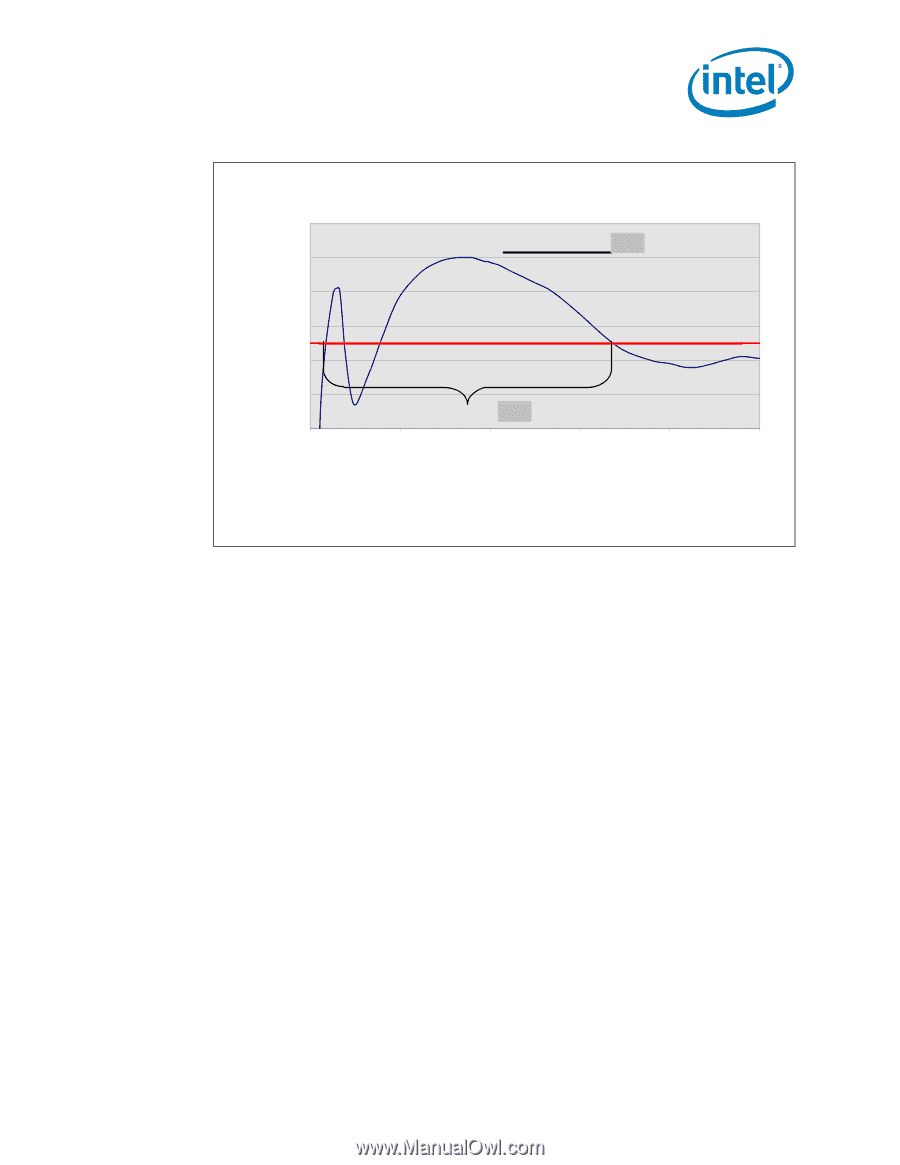
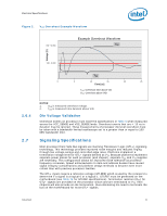
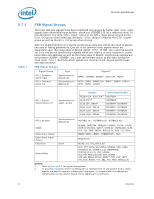
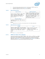
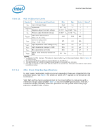
Electrical Specifications Figure 2. VCC Overshoot Example Waveform VID + 0.050 Example Overshoot Waveform VOS Voltage [V] VID - 0.000 TOS 0 5 10 15 20 25 Time [us] TOS: Overshoot time above VID VOS: Overshoot above VID 2.6.4 2.7 NOTES: 1. VOS is measured overshoot voltage. 2. TOS is measured time duration above VID. Die Voltage Validation Overshoot events on processor must meet the specifications in Table 6 when measured across the VCC_SENSE and VSS_SENSE lands. Overshoot events that are < 10 ns in duration may be ignored. These measurements of processor die level overshoot must be taken with a bandwidth limited oscilloscope set to a greater than or equal to 100 MHz bandwidth limit. Signaling Specifications Most processor Front Side Bus signals use Gunning Transceiver Logic (GTL+) signaling technology. This technology provides improved noise margins and reduced ringing through low voltage swings and controlled edge rates. Platforms implement a termination voltage level for GTL+ signals defined as VTT. Because platforms implement separate power planes for each processor (and chipset), separate VCC and VTT supplies are necessary. This configuration allows for improved noise tolerance as processor frequency increases. Speed enhancements to data and address busses have caused signal integrity considerations and platform design methods to become even more critical than with previous processor families. The GTL+ inputs require a reference voltage (GTLREF) which is used by the receivers to determine if a signal is a logical 0 or a logical 1. GTLREF must be generated on the motherboard (see Table 14 for GTLREF specifications). Termination resistors (RTT) for GTL+ signals are provided on the processor silicon and are terminated to VTT. Intel chipsets will also provide on-die termination, thus eliminating the need to terminate the bus on the motherboard for most GTL+ signals. Datasheet 21
-
 1
1 -
2
-
3
-
4
-
5
-
6
-
7
-
8
-
9
-
10
-
11
-
12
-
13
-
14
-
15
-
 16
16 -
 17
17 -
 18
18 -
 19
19 -
 20
20 -
 21
21 -
 22
22 -
 23
23 -
 24
24 -
 25
25 -
 26
26 -
27
-
28
-
29
-
30
-
31
-
32
-
33
-
34
-
35
-
36
-
37
-
38
-
39
-
40
-
41
-
42
-
43
-
44
-
45
-
46
-
47
-
48
-
49
-
50
-
51
-
52
-
53
-
54
-
55
-
56
-
57
-
58
-
59
-
60
-
61
-
62
-
63
-
64
-
65
-
66
-
67
-
68
-
69
-
70
-
71
-
72
-
73
-
74
-
75
-
76
-
77
-
78
-
79
-
80
-
81
-
82
-
83
-
84
-
85
-
86
-
87
-
88
-
89
-
90
-
91
-
92
-
93
-
94
-
95
-
96
-
97
-
98
-
99
-
100
 |
 |