Intel BX80571E5300 Data Sheet - Page 33
Package Mechanical, Specifications
 |
UPC - 735858204996
View all Intel BX80571E5300 manuals
Add to My Manuals
Save this manual to your list of manuals |
Page 33 highlights
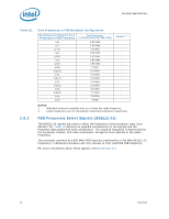
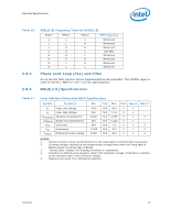
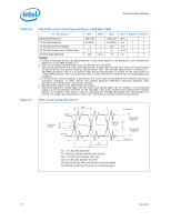
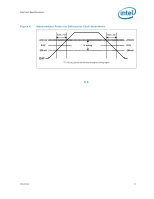
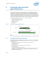
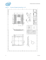
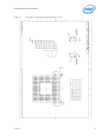
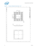
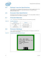
Package Mechanical Specifications 3 Package Mechanical Specifications Figure 5. The processor is packaged in a Flip-Chip Land Grid Array (FC-LGA8) package that interfaces with the motherboard via an LGA775 socket. The package consists of a processor core mounted on a substrate land-carrier. An integrated heat spreader (IHS) is attached to the package substrate and core and serves as the mating surface for processor component thermal solutions, such as a heatsink. Figure 5 shows a sketch of the processor package components and how they are assembled together. Refer to the LGA775 Socket Mechanical Design Guide for complete details on the LGA775 socket. The package components shown in Figure 5 include the following: • Integrated Heat Spreader (IHS) • Thermal Interface Material (TIM) • Processor core (die) • Package substrate • Capacitors Processor Package Assembly Sketch Core (die) TIM IHS Substrate 3.1 System Board Capacitors LGA775 Socket Processor_Pkg_Assembly_775 NOTE: 1. Socket and motherboard are included for reference and are not part of processor package. Package Mechanical Drawing The package mechanical drawings are shown in Figure 6 and Figure 7. The drawings include dimensions necessary to design a thermal solution for the processor. These dimensions include: • Package reference with tolerances (total height, length, width, etc.) • IHS parallelism and tilt • Land dimensions • Top-side and back-side component keep-out dimensions • Reference datums • All drawing dimensions are in mm [in]. • Guidelines on potential IHS flatness variation with socket load plate actuation and installation of the cooling solution is available in the processor Thermal and Mechanical Design Guidelines. Datasheet 33
-
 1
1 -
2
-
3
-
4
-
5
-
6
-
7
-
8
-
9
-
10
-
11
-
12
-
13
-
14
-
15
-
16
-
17
-
18
-
19
-
20
-
21
-
22
-
23
-
24
-
25
-
26
-
27
-
 28
28 -
 29
29 -
 30
30 -
 31
31 -
 32
32 -
 33
33 -
 34
34 -
 35
35 -
 36
36 -
 37
37 -
 38
38 -
39
-
40
-
41
-
42
-
43
-
44
-
45
-
46
-
47
-
48
-
49
-
50
-
51
-
52
-
53
-
54
-
55
-
56
-
57
-
58
-
59
-
60
-
61
-
62
-
63
-
64
-
65
-
66
-
67
-
68
-
69
-
70
-
71
-
72
-
73
-
74
-
75
-
76
-
77
-
78
-
79
-
80
-
81
-
82
-
83
-
84
-
85
-
86
-
87
-
88
-
89
-
90
-
91
-
92
-
93
-
94
-
95
-
96
-
97
-
98
-
99
-
100
 |
 |
