Intel BX80571E5300 Data Sheet - Page 82
PECI Specifications
 |
UPC - 735858204996
View all Intel BX80571E5300 manuals
Add to My Manuals
Save this manual to your list of manuals |
Page 82 highlights
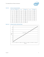
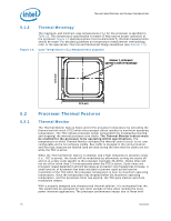
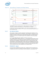
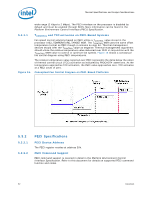
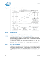
Thermal Specifications and Design Considerations wide range (2 Kbps to 2 Mbps). The PECI interface on the processor is disabled by default and must be enabled through BIOS. More information can be found in the Platform Environment Control Interface (PECI) Specification. 5.3.1.1 Figure 16. TCONTROL and TCC activation on PECI-Based Systems Fan speed control solutions based on PECI utilize a TCONTROL value stored in the processor IA32_TEMPERATURE_TARGET MSR. The TCONTROL MSR uses the same offset temperature format as PECI though it contains no sign bit. Thermal management devices should infer the TCONTROL value as negative. Thermal management algorithms should utilize the relative temperature value delivered over PECI in conjunction with the TCONTROL MSR value to control or optimize fan speeds. Figure 16 shows a conceptual fan control diagram using PECI temperatures. The relative temperature value reported over PECI represents the delta below the onset of thermal control circuit (TCC) activation as indicated by PROCHOT# assertions. As the temperature approaches TCC activation, the PECI value approaches zero. TCC activates at a PECI count of zero. Conceptual Fan Control Diagram on PECI-Based Platforms 5.3.2 5.3.2.1 5.3.2.2 PECI Specifications PECI Device Address The PECI register resides at address 30h. PECI Command Support PECI command support is covered in detail in the Platform Environment Control Interface Specification. Refer to this document for details on supported PECI command function and codes. 82 Datasheet
-
 1
1 -
2
-
3
-
4
-
5
-
6
-
7
-
8
-
9
-
10
-
11
-
12
-
13
-
14
-
15
-
16
-
17
-
18
-
19
-
20
-
21
-
22
-
23
-
24
-
25
-
26
-
27
-
28
-
29
-
30
-
31
-
32
-
33
-
34
-
35
-
36
-
37
-
38
-
39
-
40
-
41
-
42
-
43
-
44
-
45
-
46
-
47
-
48
-
49
-
50
-
51
-
52
-
53
-
54
-
55
-
56
-
57
-
58
-
59
-
60
-
61
-
62
-
63
-
64
-
65
-
66
-
67
-
68
-
69
-
70
-
71
-
72
-
73
-
74
-
75
-
76
-
 77
77 -
 78
78 -
 79
79 -
 80
80 -
 81
81 -
 82
82 -
 83
83 -
 84
84 -
 85
85 -
 86
86 -
 87
87 -
88
-
89
-
90
-
91
-
92
-
93
-
94
-
95
-
96
-
97
-
98
-
99
-
100
 |
 |
