Intel E2180 Design Guide - Page 20
Example Thermal Profile
 |
UPC - 683728169121
View all Intel E2180 manuals
Add to My Manuals
Save this manual to your list of manuals |
Page 20 highlights
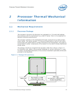
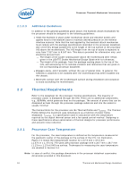
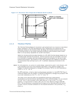
Processor Thermal/Mechanical Information Section 3.1). The intercept on the thermal profile assumes a maximum ambient operating condition that is consistent with the available chassis solutions. To determine compliance to the thermal profile, a measurement of the actual processor power dissipation is required. The measured power is plotted on the Thermal Profile to determine the maximum case temperature. Using the example in Figure 2-3 for the Intel® Core™2 Duo processor with 4 MB cache at Tc-max of 60.1 °C dissipating 50 W, the maximum case temperature is 56.2 °C. See the datasheet for the thermal profile. Figure 2-3. Example Thermal Profile 2.2.3 TCONTROL TCONTROL defines the maximum operating temperature for the digital thermal sensor when the thermal solution fan speed is being controlled by the digital thermal sensor. The TCONTROL parameter defines a very specific processor operating region where fan speed can be reduced. This allows the system integrator a method to reduce the acoustic noise of the processor cooling solution, while maintaining compliance to the processor thermal specification. Note: The TCONTROL value for the processor is relative to the Thermal Control Circuit (TCC) activation set point which will be seen as 0 via the digital thermal sensor. As a result the TCONTROL value will always be a negative number. See Chapter 4 for the discussion the thermal management logic and features and Chapter 7 on Intel® Quiet System Technology (Intel® QST). The value of TCONTROL is driven by a number of factors. One of the most significant of these is the processor idle power. As a result a processor with a high (closer to 0 ) 20 Thermal and Mechanical Design Guidelines
-
 1
1 -
2
-
3
-
4
-
5
-
6
-
7
-
8
-
9
-
10
-
11
-
12
-
13
-
14
-
 15
15 -
 16
16 -
 17
17 -
 18
18 -
 19
19 -
 20
20 -
 21
21 -
 22
22 -
 23
23 -
 24
24 -
 25
25 -
26
-
27
-
28
-
29
-
30
-
31
-
32
-
33
-
34
-
35
-
36
-
37
-
38
-
39
-
40
-
41
-
42
-
43
-
44
-
45
-
46
-
47
-
48
-
49
-
50
-
51
-
52
-
53
-
54
-
55
-
56
-
57
-
58
-
59
-
60
-
61
-
62
-
63
-
64
-
65
-
66
-
67
-
68
-
69
-
70
-
71
-
72
-
73
-
74
-
75
-
76
-
77
-
78
-
79
-
80
-
81
-
82
-
83
-
84
-
85
-
86
-
87
-
88
-
89
-
90
-
91
-
92
-
93
-
94
-
95
-
96
-
97
-
98
-
99
-
100
-
101
-
102
-
103
-
104
-
105
-
106
-
107
-
108
-
109
-
110
-
111
-
112
-
113
-
114
-
115
-
116
-
117
-
118
-
119
-
120
-
121
-
122
-
123
-
124
-
125
-
126
-
127
-
128
-
129
-
130
-
131
-
132
-
133
-
134
-
135
-
136
-
137
-
138
-
139
-
140
-
141
-
142
-
143
-
144
-
145
-
146
-
147
-
148
 |
 |
