Intel E2180 Design Guide - Page 70
Output Weighting Matrix, Proportional-Integral-Derivative PID
 |
UPC - 683728169121
View all Intel E2180 manuals
Add to My Manuals
Save this manual to your list of manuals |
Page 70 highlights
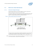
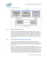
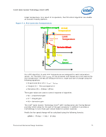
Intel® Quiet System Technology (Intel® QST) Figure 7-1. Intel® QST Overview Intel® QST Temperature sensing and response Calculations (PID) Fan to sensor Relationship (Output Weighting Matrix) PECI / SST Fan Commands (PID) PWM Temperature Sensors Fans System Response 7.1.1 7.1.2 Output Weighting Matrix Intel QST provides an Output Weighting Matrix that provides a means for a single thermal sensor to affect the speed of multiple fans. An example of how the matrix could be used is if a sensor located next to the memory is sensitive to changes in both the processor heatsink fan and a 2nd fan in the system. By placing a factor in this matrix additional the Intel QST could command the processor thermal solution fan and this 2nd fan to both accelerate a small amount. At the system level these two small changes can result in a smaller change in acoustics than having a single fan respond to this sensor. Proportional-Integral-Derivative (PID) The use of Proportional-Integral-Derivative (PID) control algorithms allow the magnitude of fan response to be determined based upon the difference between current temperature readings and specific temperature targets. A major advantage of a PID Algorithm is the ability to control the fans to achieve sensor temperatures much closer to the TCONTROL. Figure 7-2 is an illustration of the PID fan control algorithm. As illustrated in the figure, when the actual temperature is below the target temperature, the fan will slow down. The current FSC devices have a fixed temperature vs. PWM output relationship and miss this opportunity to achieve additional acoustic benefits. As the actual temperature starts ramping up and approaches the target temperature, the algorithm will instruct the fan to speed up gradually, but will not abruptly increase the fan speed to respond to the condition. It can allow an overshoot over the target temperature for a short period of time while ramping up the fan to bring the actual temperature to the 70 Thermal and Mechanical Design Guidelines
-
 1
1 -
2
-
3
-
4
-
5
-
6
-
7
-
8
-
9
-
10
-
11
-
12
-
13
-
14
-
15
-
16
-
17
-
18
-
19
-
20
-
21
-
22
-
23
-
24
-
25
-
26
-
27
-
28
-
29
-
30
-
31
-
32
-
33
-
34
-
35
-
36
-
37
-
38
-
39
-
40
-
41
-
42
-
43
-
44
-
45
-
46
-
47
-
48
-
49
-
50
-
51
-
52
-
53
-
54
-
55
-
56
-
57
-
58
-
59
-
60
-
61
-
62
-
63
-
64
-
 65
65 -
 66
66 -
 67
67 -
 68
68 -
 69
69 -
 70
70 -
 71
71 -
 72
72 -
 73
73 -
 74
74 -
 75
75 -
76
-
77
-
78
-
79
-
80
-
81
-
82
-
83
-
84
-
85
-
86
-
87
-
88
-
89
-
90
-
91
-
92
-
93
-
94
-
95
-
96
-
97
-
98
-
99
-
100
-
101
-
102
-
103
-
104
-
105
-
106
-
107
-
108
-
109
-
110
-
111
-
112
-
113
-
114
-
115
-
116
-
117
-
118
-
119
-
120
-
121
-
122
-
123
-
124
-
125
-
126
-
127
-
128
-
129
-
130
-
131
-
132
-
133
-
134
-
135
-
136
-
137
-
138
-
139
-
140
-
141
-
142
-
143
-
144
-
145
-
146
-
147
-
148
 |
 |
