Intel E2180 Design Guide - Page 50
Safety Requirements, Geometric Envelope for Intel Reference BTX, Thermal Module Assembly
 |
UPC - 683728169121
View all Intel E2180 manuals
Add to My Manuals
Save this manual to your list of manuals |
Page 50 highlights
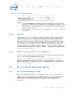
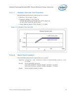
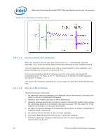
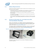
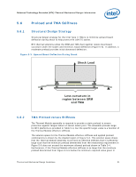
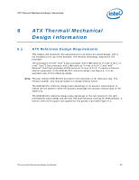
Balanced Technology Extended (BTX) Thermal/Mechanical Design Information 5.4 Safety Requirements Heatsink and attachment assemblies shall be consistent with the manufacture of units that meet the safety standards: • UL Recognition-approved for flammability at the system level. All mechanical and thermal enabling components must be a minimum UL94V-2 approved. • CSA Certification. All mechanical and thermal enabling components must have CSA certification. • All components (in particular the heatsink fins) must meet the test requirements of UL1439 for sharp edges. • If the International Accessibility Probe specified in IEC 950 can access the moving parts of the fan, consider adding safety feature so that there is no risk of personal injury. 5.5 Geometric Envelope for Intel Reference BTX Thermal Module Assembly Figure 7-50 through Figure 7-54 in Appendix H gives the motherboard keep-out information for the BTX thermal mechanical solutions. Additional information on BTX design considerations can be found in Balanced Technology Extended (BTX) System Design Guide available at http://www.formfactors.org. The maximum height of the TMA above the motherboard is 60.60 mm [2.386 inches], for compliance with the motherboard primary side height constraints defined in the BTX Interface Specification for Zone A, found at http://www.formfactors.org. Figure 5-4. Intel Type II TMA 65 W Reference Design Development vendor information for the Intel Type II TMA Reference Solution is provided in Appendix I. 50 Thermal and Mechanical Design Guidelines
-
 1
1 -
2
-
3
-
4
-
5
-
6
-
7
-
8
-
9
-
10
-
11
-
12
-
13
-
14
-
15
-
16
-
17
-
18
-
19
-
20
-
21
-
22
-
23
-
24
-
25
-
26
-
27
-
28
-
29
-
30
-
31
-
32
-
33
-
34
-
35
-
36
-
37
-
38
-
39
-
40
-
41
-
42
-
43
-
44
-
 45
45 -
 46
46 -
 47
47 -
 48
48 -
 49
49 -
 50
50 -
 51
51 -
 52
52 -
 53
53 -
 54
54 -
 55
55 -
56
-
57
-
58
-
59
-
60
-
61
-
62
-
63
-
64
-
65
-
66
-
67
-
68
-
69
-
70
-
71
-
72
-
73
-
74
-
75
-
76
-
77
-
78
-
79
-
80
-
81
-
82
-
83
-
84
-
85
-
86
-
87
-
88
-
89
-
90
-
91
-
92
-
93
-
94
-
95
-
96
-
97
-
98
-
99
-
100
-
101
-
102
-
103
-
104
-
105
-
106
-
107
-
108
-
109
-
110
-
111
-
112
-
113
-
114
-
115
-
116
-
117
-
118
-
119
-
120
-
121
-
122
-
123
-
124
-
125
-
126
-
127
-
128
-
129
-
130
-
131
-
132
-
133
-
134
-
135
-
136
-
137
-
138
-
139
-
140
-
141
-
142
-
143
-
144
-
145
-
146
-
147
-
148
 |
 |