Intel E2180 Design Guide - Page 51
Preload and TMA Stiffness
 |
UPC - 683728169121
View all Intel E2180 manuals
Add to My Manuals
Save this manual to your list of manuals |
Page 51 highlights
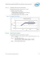
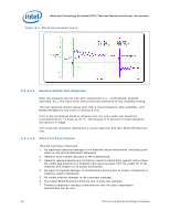
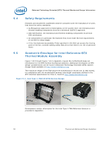
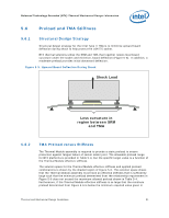
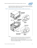
Balanced Technology Extended (BTX) Thermal/Mechanical Design Information 5.6 Preload and TMA Stiffness 5.6.1 Structural Design Strategy Structural design strategy for the Intel Type II TMA is to minimize upward board deflection during shock to help protect the LGA775 socket. BTX thermal solutions utilize the SRM and TMA that together resists local board curvature under the socket and minimize, board deflection (Figure 5-5). In addition, a moderate preload provides initial downward deflection. Figure 5-5. Upward Board Deflection During Shock Shock Load Less curvature in region between SRM and TMA 5.6.2 TMA Preload versus Stiffness The Thermal Module assembly is required to provide a static preload to ensure protection against fatigue failure of socket solder joint. The allowable preload range for BTX platforms is provided in Table 5-4, but the specific target value is a function of the Thermal Module effective stiffness. The solution space for the Thermal Module effective stiffness and applied preload combinations is shown by the shaded region of Figure 5-6. This solution space shows that the Thermal Module assembly must have an effective stiffness that is sufficiently large such that the minimum preload determined from the relationship requirement in Figure 5-6 does not exceed the maximum allowed preload shown in Table 5-4. Furthermore, if the Thermal Module effective stiffness is so large that the minimum preload determined from Figure 5-6 is below the minimum required value given in Thermal and Mechanical Design Guidelines 51
-
 1
1 -
2
-
3
-
4
-
5
-
6
-
7
-
8
-
9
-
10
-
11
-
12
-
13
-
14
-
15
-
16
-
17
-
18
-
19
-
20
-
21
-
22
-
23
-
24
-
25
-
26
-
27
-
28
-
29
-
30
-
31
-
32
-
33
-
34
-
35
-
36
-
37
-
38
-
39
-
40
-
41
-
42
-
43
-
44
-
45
-
 46
46 -
 47
47 -
 48
48 -
 49
49 -
 50
50 -
 51
51 -
 52
52 -
 53
53 -
 54
54 -
 55
55 -
 56
56 -
57
-
58
-
59
-
60
-
61
-
62
-
63
-
64
-
65
-
66
-
67
-
68
-
69
-
70
-
71
-
72
-
73
-
74
-
75
-
76
-
77
-
78
-
79
-
80
-
81
-
82
-
83
-
84
-
85
-
86
-
87
-
88
-
89
-
90
-
91
-
92
-
93
-
94
-
95
-
96
-
97
-
98
-
99
-
100
-
101
-
102
-
103
-
104
-
105
-
106
-
107
-
108
-
109
-
110
-
111
-
112
-
113
-
114
-
115
-
116
-
117
-
118
-
119
-
120
-
121
-
122
-
123
-
124
-
125
-
126
-
127
-
128
-
129
-
130
-
131
-
132
-
133
-
134
-
135
-
136
-
137
-
138
-
139
-
140
-
141
-
142
-
143
-
144
-
145
-
146
-
147
-
148
 |
 |
