JVC GY-DV700WUCL Instruction Manual - Page 23
Lens (optional), ZOOM mode knob
 |
View all JVC GY-DV700WUCL manuals
Add to My Manuals
Save this manual to your list of manuals |
Page 23 highlights
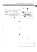
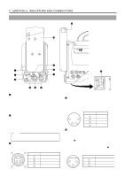
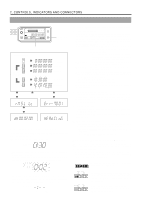
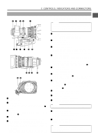
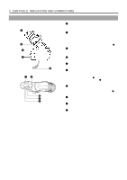
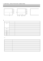
2. CONTROLS, INDICATORS AND CONNECTORS 2-7 Lens (optional) A19 × 8.7BW t r ew q & IF 19x ft ∞ m 8.7 8 5.6 4 2.8 TV . ZOOM LENS 20 1.8 F.f MACRO 40 80 165 FUJI PHOTO QUICK Z or RET FUJIN0N A19x8.7BW (A19x8.7BRRM-39) 1:1.8/8.7-165 MADE IN JAPAN by FUJI PHOTO OPTICAL CO., LTD. mm M A W T y u i o !0 !1 20 M ACR TV - ZOOM O C 16 11 8 5.6 m ∞ ft 8.7 10 30 5 7 10 15 ASPHERIC & IF 19x 3 2 5 1.5 FUJINON !6 !7 !2 !3 !4 !5 S ALQLUOICCKATZIOOSOWNMITCH RET Q . Z VTR Q . Z MOM Q . Z 1 FOCUS ring Manual focus ring. 2 ZOOM lever/ring This is the manual zoom ring equipped with a zoom lever. To activate the zoom feature on, turn the zoom mode knob 12 to position "M". 3 IRIS ring Manual Iris ring. To activate the auto iris feature, set the Iris Mode switch 10 to A. 4 Macro lever Pull this lever up to enable the rotation of the macro ring. 5 Macro focusing ring (for close-up shooting) By rotating this ring in the direction of the arrow, the lens becomes capable of close-up shooting of very small objects. Normal focus adjustment and zooming are not available in the macro mode. To shoot images in the macro mode, set the focus ring to the infinite position and the zoom ring to the widest angle position. To adjust the focus of the macro image, rotate this ring in the direction of arrow until the object is focused. Note : The back-focus knob is located close to the macro ring, be careful not to mistake the back-focus knob for the macro ring. After the required operation, be sure to return the macro ring to the normal position. 6 BACK FOCUS ring/fixing screw For Set-up Back Focus adjustment only. Secure with the Screw knob after adjustment. 7 [VTR] trigger button To start shooting push once. To stop shooting push again. 8 [RET] return video button The return video signal from the VCR section can be monitored on the viewfinder only while pushing this button. • The Viewfinder Status display is not available during this operation. 9 ZOOM servo control lever Pushing this lever in the W direction makes the lens move wider. Pushing this lever in the T direction makes the lens move tighter. Pushing harder changes the speed of the Zoom. To operate the servo zoom feature with this lever, set the ZOOM knob 12 to S. 10 IRIS mode switch A : Activates the auto iris feature. M : Allows manual iris control. 11 Momentary auto iris button When the IRIS MODE switch 10 is at M, pushing this button activates the Auto Iris Function while it is held down only. 12 ZOOM mode knob S : Servo Zoom mode. Allows operation by the Zoom Servo Control lever 9 . M : Manual Zoom mode. Allows zoom control by the Zoom lever/ring 2 . 13 REMOTE FOCUS control connector To connect with an optional focus servo unit. 14 ZOOM servo connector Connect with an optional zoom servo unit. 15 Aspect ratio switching lever Switches the aspect ratio between 4:3 and 16:9. Note : Make sure to switch the lever to the correct position. 16 Rapid zoom setting switch Quickly sets the zoom to telescopic mode. For the setting method, refer to the "OPERATION MANUAL" for the lens. 17 IRIS speed adjusting control Adjusts the iris operation speed. Memo : If the speed becomes too fast, hunting may occur. To avoid the phenomena described above, perform adjustment again. 23
-
 1
1 -
2
-
3
-
4
-
5
-
6
-
7
-
8
-
9
-
10
-
11
-
12
-
13
-
14
-
15
-
16
-
17
-
 18
18 -
 19
19 -
 20
20 -
 21
21 -
 22
22 -
 23
23 -
 24
24 -
 25
25 -
 26
26 -
 27
27 -
 28
28 -
29
-
30
-
31
-
32
-
33
-
34
-
35
-
36
-
37
-
38
-
39
-
40
-
41
-
42
-
43
-
44
-
45
-
46
-
47
-
48
-
49
-
50
-
51
-
52
-
53
-
54
-
55
-
56
-
57
-
58
-
59
-
60
-
61
-
62
-
63
-
64
-
65
-
66
-
67
-
68
-
69
-
70
-
71
-
72
-
73
-
74
-
75
-
76
-
77
-
78
-
79
-
80
-
81
-
82
-
83
-
84
-
85
-
86
-
87
-
88
-
89
-
90
-
91
-
92
-
93
-
94
-
95
 |
 |
