JVC VN-C205U Instructions - Page 18
Connection to Alarm Input/Output Terminal, 2 Mounting the Camera to the Ceiling Continued, Caution
 |
UPC - 046838021497
View all JVC VN-C205U manuals
Add to My Manuals
Save this manual to your list of manuals |
Page 18 highlights
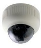
Preparation (Step 1 Connection/Installation) 1-2 Mounting the Camera to the Ceiling (Continued) 1. Preparations (Continued) Ⅵ Connection to Alarm Input/Output Terminal 1 1 Flathead Screwdriver Flathead Screwdriver 3 2 4 mm (1/8 inches) Alarm Signal Cable Connect the alarm input/output terminals to external devices such as sensors and buzzers. 1 Loosen the screws on both edges of the terminal block using a flathead screwdriver, followed by dismantling it as shown in the left diagram. 2 Strip the coating of the alarm signal cable by about 4mm (1/8 inches) before inserting it into the terminal. 3 Turn the screw on the side to fasten the alarm signal cable. * Connect the alarm terminal according to step 4 of "2 Installation." (☞ Page 20) Note Cable Specifications 50 m or shorter in length UL1007, UL1015 or equivalent AWG#22 to AWG#18 or equivalent ● Alarm Input Terminal VN-C205 DC12V R OUT Sensor Connection Example (1) VCC R 12V 1.2mA Grounding GND Terminal (Alarm Input Equivalent Circuit) OUT Sensor Connection Example (2) Relay, switch, etc. Caution Due to external noise, the cable may not function properly even when the cable length is less than 50 m. In this case, use a shielded cable or take measures such as keeping the cable away from the noise source. Connect this terminal to an infrared, door or metallic sensor, or to a manual switch. Input Requirements ● No-voltage relay or NPN open collector input ● The polarity of input detection can be selected via software ● Make/Break/Toggle (at least 250 ms) ● Circuit current at low-level: 1.2 mA ● Voltage applied at high level: 12 V GND 18
-
 1
1 -
2
-
3
-
4
-
5
-
6
-
7
-
8
-
9
-
10
-
11
-
12
-
 13
13 -
 14
14 -
 15
15 -
 16
16 -
 17
17 -
 18
18 -
 19
19 -
 20
20 -
 21
21 -
 22
22 -
 23
23 -
24
-
25
-
26
-
27
-
28
-
29
-
30
-
31
-
32
-
33
-
34
-
35
-
36
-
37
-
38
-
39
-
40
 |
 |
