JVC VN-C205U Instructions - Page 21
Wrap insulation tape around cables., Point the camera in the direction you, wish to capture.
 |
UPC - 046838021497
View all JVC VN-C205U manuals
Add to My Manuals
Save this manual to your list of manuals |
Page 21 highlights
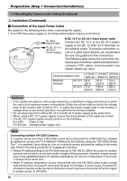
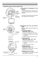
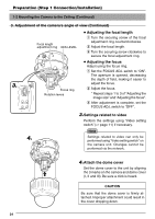
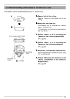
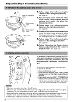
6. Wrap with tape BNC Connector 7. Horizontal Lock screw Mounting holes 8. Input power cable connection Wrap with tape 6. Wrap insulation tape around cables. As shown in the diagram to the left, wrap insulation tape around the input power cable connection and BNC connector. Insert the cables into the hole in the ceiling. Note Wrapping the wires with insulation tape improves handling as well as reducing interference. LAN cable 7. Point the camera in the direction you Alarm signal cable wish to capture. Point the camera so that the Horizontal Lock screw is facing the direction you wish to capture. The camera can be adjusted ±60˚ horizontally to either side of the Horizontal Lock screw. 8. Mount the camera to the ceiling. Use M4-sized (No. 8) screws/bolts or wood screws (4.1mm, 1/8 inches) to secure the camera in four places when mounting to the ceiling or wall. Mounting holes Caution Tighten all screws securely. Otherwise the camera may come loose and fall. Screws 21
-
 1
1 -
2
-
3
-
4
-
5
-
6
-
7
-
8
-
9
-
10
-
11
-
12
-
13
-
14
-
15
-
 16
16 -
 17
17 -
 18
18 -
 19
19 -
 20
20 -
 21
21 -
 22
22 -
 23
23 -
 24
24 -
 25
25 -
 26
26 -
27
-
28
-
29
-
30
-
31
-
32
-
33
-
34
-
35
-
36
-
37
-
38
-
39
-
40
 |
 |
