JVC VN-C205U Instructions - Page 20
Installation, 2 Mounting the Camera to the Ceiling Continued
 |
UPC - 046838021497
View all JVC VN-C205U manuals
Add to My Manuals
Save this manual to your list of manuals |
Page 20 highlights
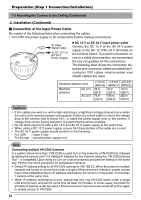
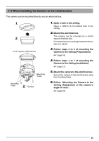
Preparation (Step 1 Connection/Installation) 1-2 Mounting the Camera to the Ceiling (Continued) 2. Installation 1. Video signal cable Safety cable 2 . 1. Attach the safety cable to the ceiling Attach to ceiling slab Alarm signal cable slab. (Safety cable not included) Attach the safety cable that has already been attached to the camera to the ceiling slab or channel. Make sure that the wire is attached 5. Solder or crimp securely. 2. Connect the video signal cable. Connect the coaxial cables (BNC) to the video Insulation tape signal output connector (BNC). Input power supply cable LAN cable Cable RG-59 RG-6 Maximum length (No cable compensator) 200m (650 ft) 350m (1140 ft) 4 . RG-11 450m (1470 ft) 3. Connect the LAN cable Alarm Signal Cable Pass the LAN cable coming out from the ceiling under the plate for depressing cables, connect it to the 10BASE-T/100BASE-TX Terminal of the camera unit. 3 . 10 BASE -T/100 BASE-TX Terminal LAN cable Caution The use of a crossover cable may not be supported by certain LAN boards on some rare occasions. As such, please check your LAN board specifications before connection. Note When using 100 BASE-TX, ensure to use a Category 5 (or higher) cable. 4. Connect the alarm terminal Connect the alarm cable wired in step 5 of Preparations (☞ page 17) to the alarm terminal of camera unit. Pass the cable under the plate for depressing cables same as step 3 before connecting. 5. Connect the input power supply cable. Connect the cable protruding from the ceiling to the input power cable. (☞ Page 22) Note The input power cable uses materials similar to those of machinery wiring, so wrap the cable with insulation tape to prevent it from becoming damaged when mounting the camera. Use durable wiring for the input power cable. 20
-
 1
1 -
2
-
3
-
4
-
5
-
6
-
7
-
8
-
9
-
10
-
11
-
12
-
13
-
14
-
 15
15 -
 16
16 -
 17
17 -
 18
18 -
 19
19 -
 20
20 -
 21
21 -
 22
22 -
 23
23 -
 24
24 -
 25
25 -
26
-
27
-
28
-
29
-
30
-
31
-
32
-
33
-
34
-
35
-
36
-
37
-
38
-
39
-
40
 |
 |
